|
|


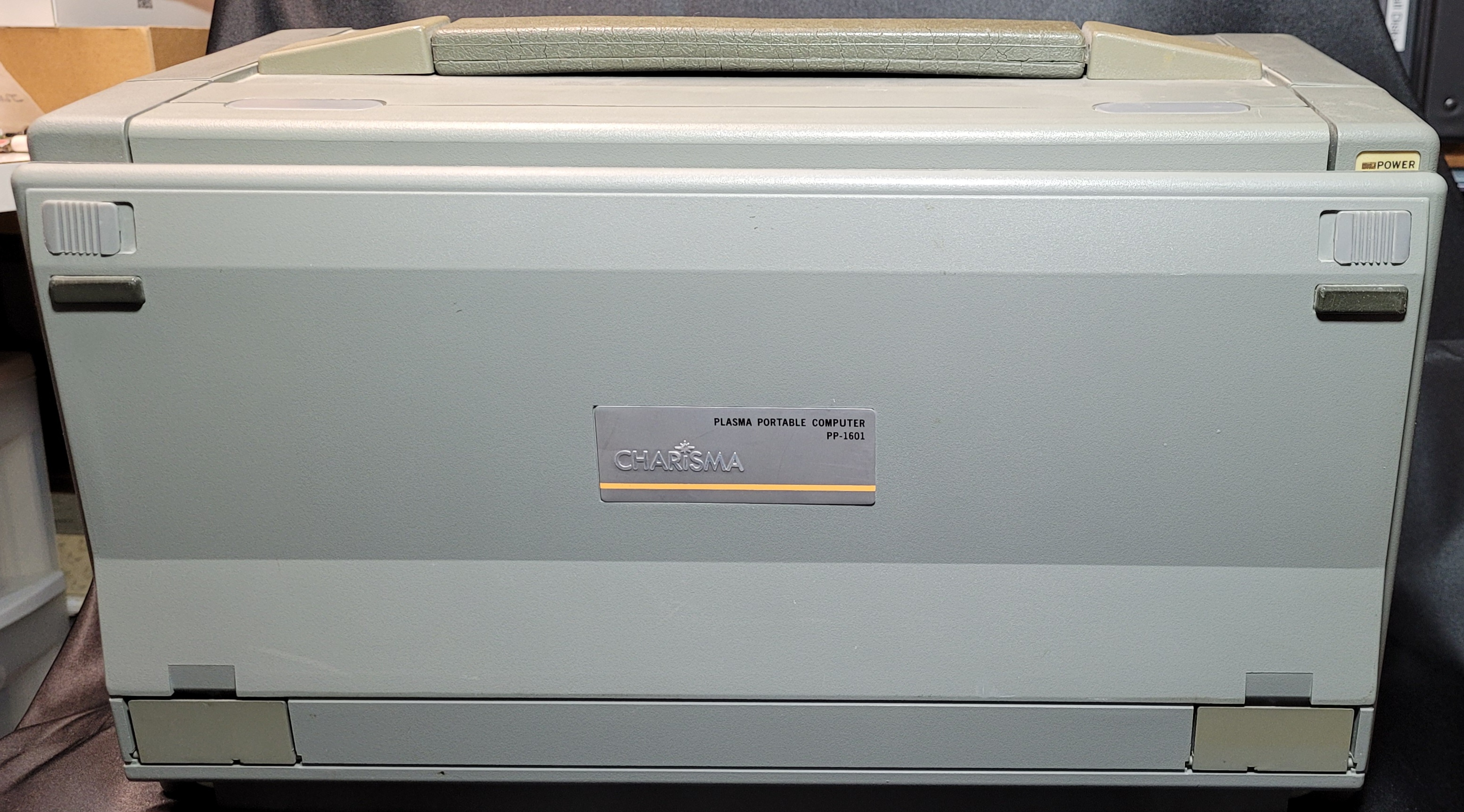


Charisma Lunchbox
PC Upgrade Project
I've had this 'lunchbox' style computer for a long time. I obtained it as part of one of the many lots of computer equipment that I bid
on over a span of several years, long ago when I used to go to the military auctions at Vandenberg AFB, and decided to keep it. I
had never seen one before and liked the 'portability' of it (although it was a bit heavy). It had a 286 motherboard if I rememberr
correctly (no longer have it though), 5 expansion slots and a nice handle for carrying.
When I first tested it I discovered that the nice amber-orange plasma display only worked on half of the screen area. I disassembled it and removed the full-length video card, replacing it with another video card I had on hand (can't remember if it was EGA or CGA or monochrome) and connected an external monitor to continue testing it, finding that it was now functional. I did search for a while for a replacement screen, unsuccessfully, so shelved it for a long time.
At one point I pulled it out again and decided to see if I could upgrade it with a newer motherboard and peripheral cards. I had a mini-AT board (with 6x86L processor) which had the board components placed such that I only had to do minimal mods to the metal drive bay inside to make it fit, so went ahead with the upgrade. I also added a new hard drive and 3.5" floppy and Windows95 OS. I still had to use an external monitor though, so didn't use it very long and shelved it again. The good thing was I discovered that a mini AT/X board could fit in it which opened up a lot of possibilities.
I've more recently regained interest in working on it but discovered that these "Charisma" lunchbox computers seem to be pretty rare, at least judging by how little I was able to find online on them.
It's now 2025... I pulled it out again about a week ago and started fiddling with it again, deciding to document the journey this time. For whatever reason, I couldn't get it to power up at all and assumed the really old power supply (PS) had bit the dust. Not giving up, I decided to replace the PS internals with a new mini-ATX PS, installing the board inside the old gutted PS enclosure... and so began this project to once again upgrade the old lunchbox PC.
I will not attempt to upgrade it to the very latest technology as I don't see the need for that (and those motherboards won't fit anyway). I have only a few motherboards I think might work in the very tight confines of the inside of this thing. One is of the 586 vintage that might fit with a little additional metal modification in the box, and if this works I would like to try some version of Linux for the OS if I can find one that will work with only 256M memory. I ordered and received a nice little 11.6" color LCD monitor that will replace the old gas-discharge display, and will just fit within the monitor enclosure. I may replace the plexiglass faceplate with a new one to allow for the larger screen display area and the menu control board. It has HDMI and VGA inputs so will work with a variety of video cards. This is a work in progress, so I will add in detail as the project continues.
4-18-25 The upgrade is beginning to move along - here are some photos and descriptions as to what's happening - - -
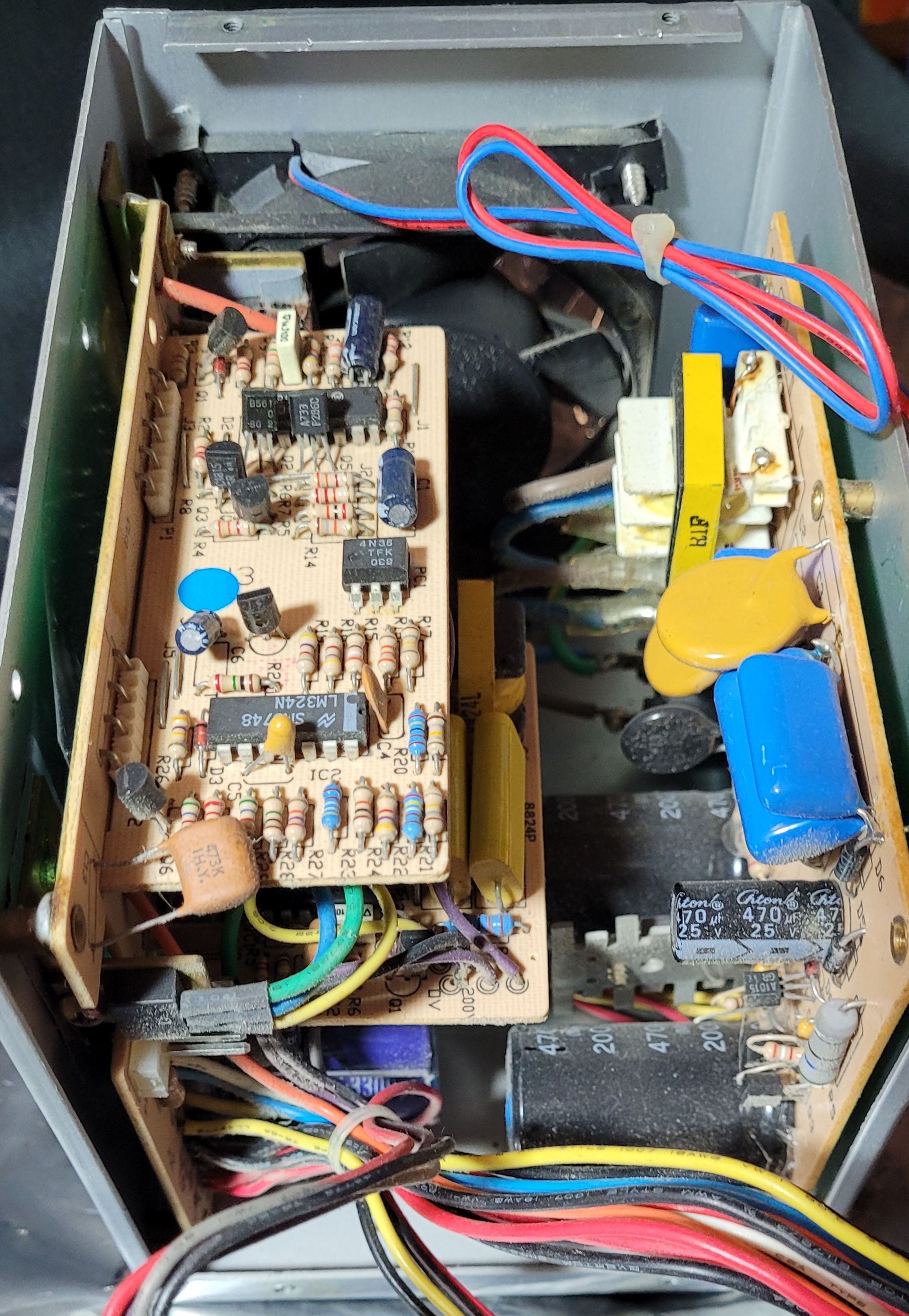
The old power supply (only 120W) refuses to work any
more and is really under-powered anyway for what I want to
do with this project.
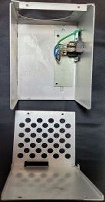
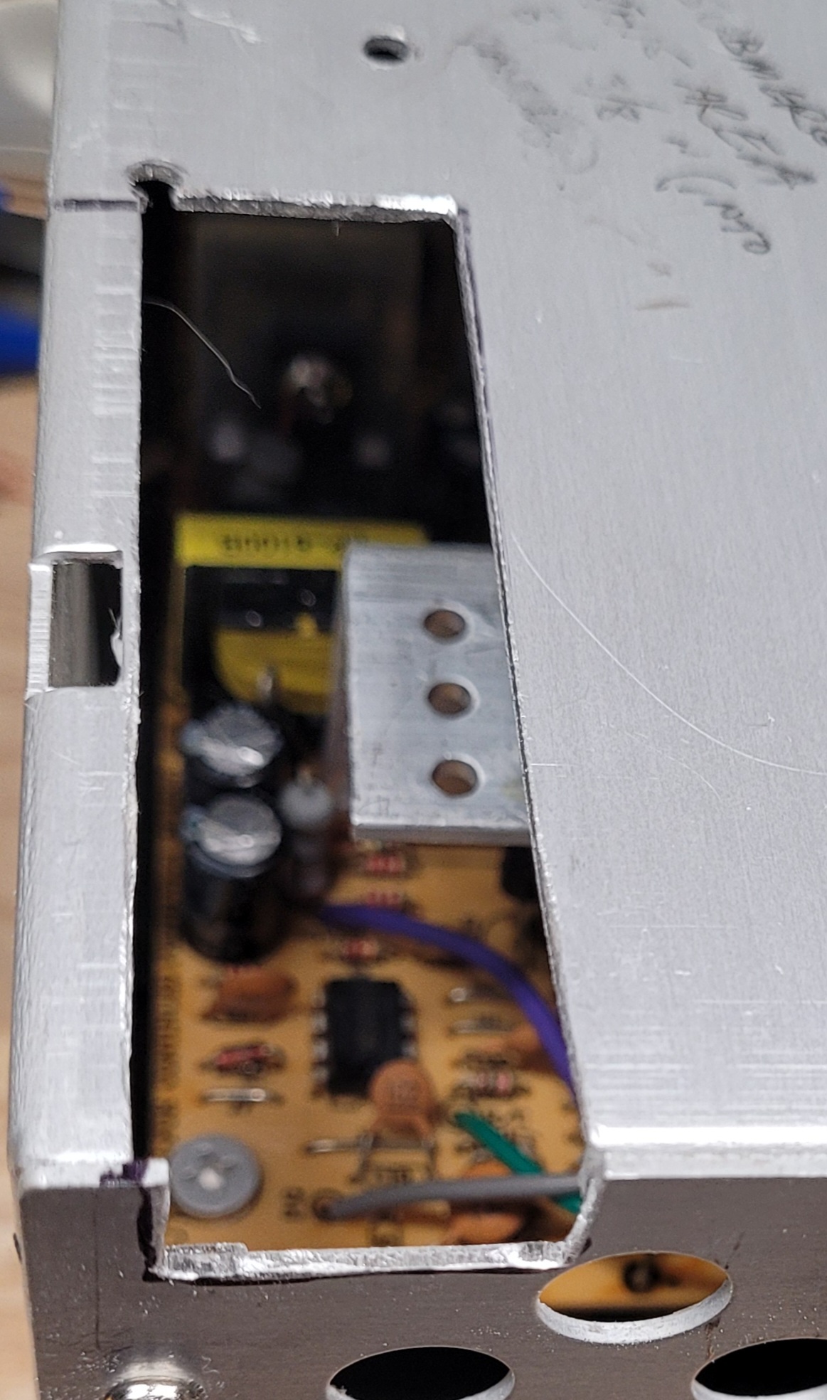
As you can see, the existing power supply is pretty complicated compared to the much more compact power supplies now available (mini-ATX style). After removing quite a few screws I was able to completely remove the existing boards and fan, leaving a blank box in which to mount a new power supply, shown far-right still in its case. The middle photo shows how the entire mini-ATX fits inside the empty PS case, so there's plenty of room to work with. There is a reason the original PS case must be reused which will be shown later.
As you can see, the existing power supply is pretty complicated compared to the much more compact power supplies now available (mini-ATX style). After removing quite a few screws I was able to completely remove the existing boards and fan, leaving a blank box in which to mount a new power supply, shown far-right still in its case. The middle photo shows how the entire mini-ATX fits inside the empty PS case, so there's plenty of room to work with. There is a reason the original PS case must be reused which will be shown later.
Power Supply Upgrade
The internals (board
and fan) were
removed from the
mini-ATX case, to be
installed into the
empty Lunchbox PC
power supply case.
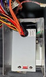
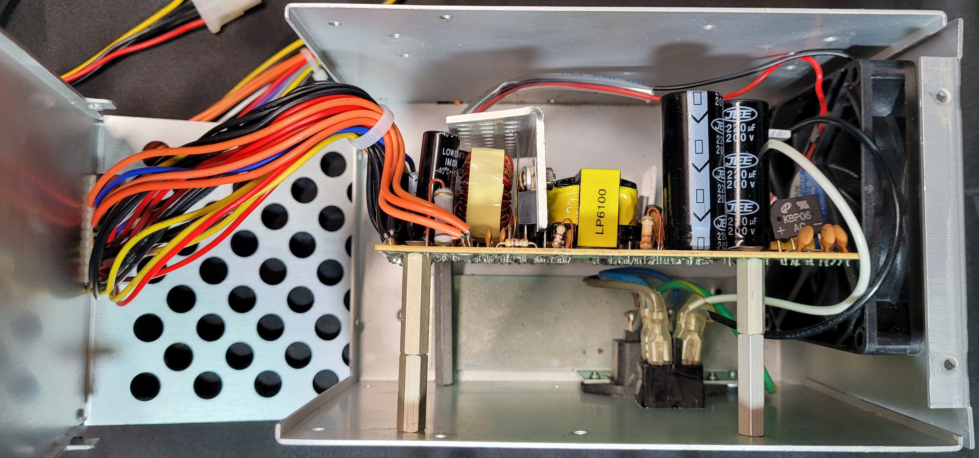
Long PC board stand-offs were used to space the board
out past the AC jack and power switch wiring. The
stand-offs were first mounted to the board, then the
board positioned inside the case (fan was already install
prior), and stand-offs were marked where they landed.
The mark positions were measured and the marks
transferred to the outside of the case for drilling. Once
the holes were drilled the board was secured to the
case and the wires routed through the existing slot in
the other case half.
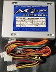
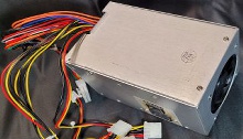
Here's the completed power supply,
upgraded from 120W capacity to
320W, sufficient for the purposes of
this project.
I tested it and it powered up just fine so now on to the next phase of the upgrade........
I tested it and it powered up just fine so now on to the next phase of the upgrade........
First I need to test the new color display (gotta be sure I can actually use it prior to continuing)... I'm going to use the same
motherboard I had in it before with a VGA board connected to the VGA input of the new display and see how it works before
progressing to installing the display in place of the old plasma display in the next phase. I'm still not sure if I want to try to install
the newer motherboard (with an AMD K6-2 processor) as I will have to do more extensive mods to the metal inside the case.
Anyway, for the test at least I'll use the older board I've had in it since the first update.
4-26-25 Having trouble getting either of my candidate motherboards to post so need to come up with a 'test bed ' using known
good boards to test each motherboard, the power supply, and other components to determine what is causing the problems. It
may be that my two motherboards have major issues, and this procedure will help me determine that.
5-3-25 With the help of two of my old tower computers and a few VGA board I was able to determine that BOTH of the motherboards I had that would fit within the lunchbox case were non-functional... bummer! I may try to repair them in the future but inside another of my old towers I found a third motherboard that looks like it will fit, and it is working! So I plan to extract that board from the tower and install it into the lunchbox case soon to do fit-checks with the rest of the hardware that goes in there.
5-30-25 Finally some progress... The motherboard I took out of the old tower was usable inside the lunchbox case, with some further modification of the interior metalwork, and with that I was able to continue with the upgrade project.
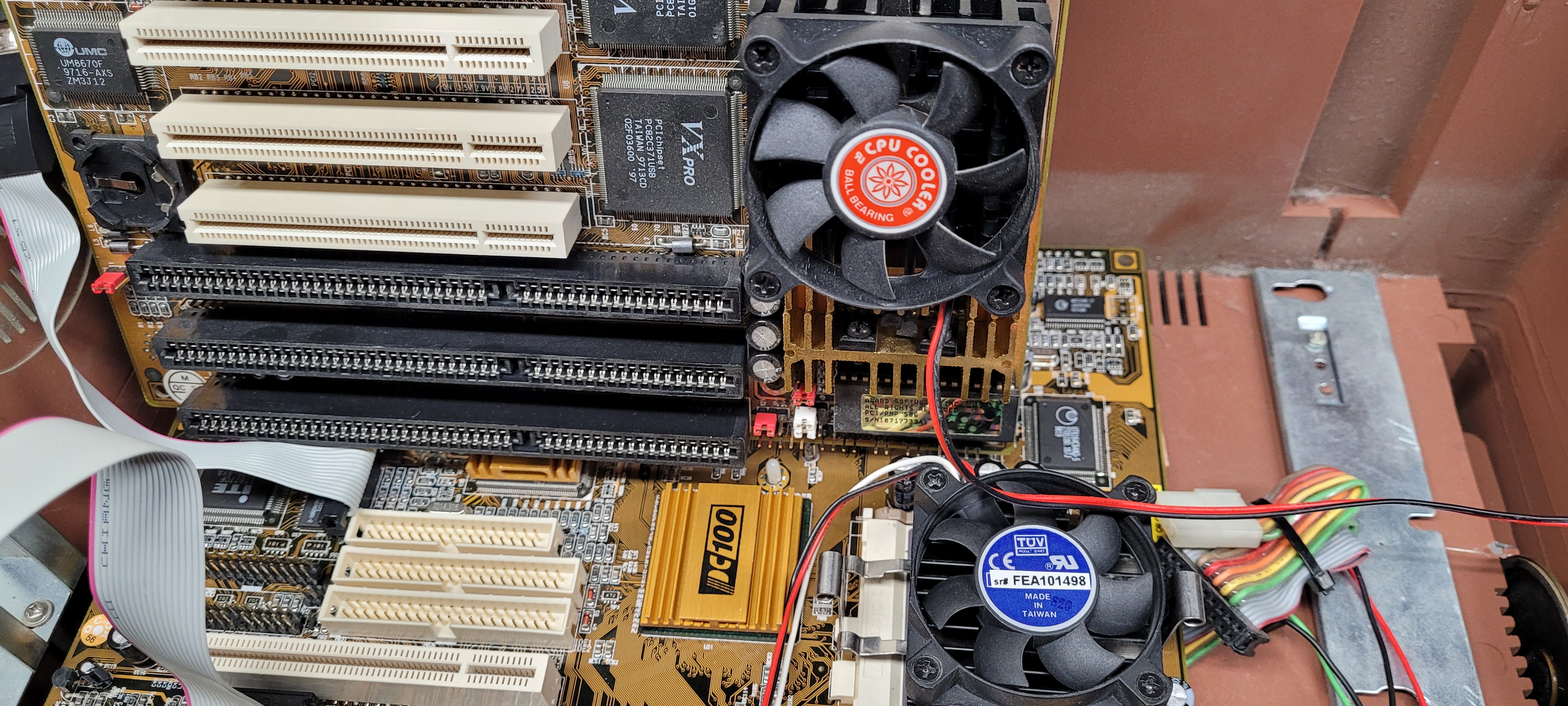
The 'new' motherboard (from the old tower computer case) ended up being longer than the baby-AT board it replaced but was
roughly similar in layout with regard to the placement of the memory SIMM / DIMM slots and the CPU, which was important.
Below is a photo comparing the newly installed motherboard in place and the old one stood up above it to show the difference
in length.
One really great feature of this board is that it has on-board VGA video via a 16-pin header, which made it possible to directly connect the new color display to the motherboard instead of kluging it to a VGA board somehow. This greatly simplified getting the display working as I had intended with this whole upgrade. Again, click the photos to see the larger versions.
One really great feature of this board is that it has on-board VGA video via a 16-pin header, which made it possible to directly connect the new color display to the motherboard instead of kluging it to a VGA board somehow. This greatly simplified getting the display working as I had intended with this whole upgrade. Again, click the photos to see the larger versions.
This pic shows the size difference of the old board (standing up) to the 'new' one (laying down).
You can see it is about 2" longer. This caused the need to further modify the metal CD / HD /
FD housing that sits directly above the board. The bottom of this housing had to be further
opened up to allow clearance for the CPU heat sink and fan (see below). I had to also cut some
clearance slots for the memory DIMM's (taller than the DIMM's) into the drive housing and
support bracket, as well as the power supply housing (also shown below).
Bracket cut for DIMM clearance
CPU fan clearance cut
To the right are some of the clearance modifications
I had to make for the CPU fan to fit (it protruded
through the bottom of the drive housing) and the
drive housing support bracket clearance for the
SIMM's.
Since the DIMM memory is taller than the old SIMM
memory that was used in the older board I had to make
more cuts for clearance to allow for the taller modules.
this involved the power supply in addition to the drive
support bracket. I first tried using a dremel tool to make
the cuts but it turned out to be tedious and the good
old hack saw did cleaner cuts and was quite a bit
faster. Of course I took the PS case apart and remove
the PS board so as to keep the metal from cutting and
filing from getting into the electronics and wreaking
havoc. It's hard to tell from the photos how this provides
clearance until you see all the parts assembled.
Another slot (or two) are required in the disk drive housing to clear
the taller DIMM modules. One is shown here and I will need another
elongated slot in the bottom corner of the housing extending to the
end of the DIMM socket to clear a second DIMM if installed.
To the left is a progression of steps to give a finished look of sorts to the drive bay. The
drives (a CDR drive and a 1.44M floppy). The left photo shows the open area left after
mounting the drives where I wanted them. There is a reason for the placement of the
floppy drive... It had to be high enough and to one edge to allow for enough clearance and
air flow for the CPU cooling fan which protrudes into the drive bay from below. I had a box
of blank bay covers so selected one with the intent to modify it to surround the floppy
drive. I did some careful measuring and marking on the blank (center photo), then
carefully cut using a hacksaw. The cuts came out very straight and I only had to clear the
leftover plastic using an exacto blade to clean it up. I installed it and it fit perfectly in
place as seen in the right photo.
It might appear that I mounted the CDR drive in upside-down but I wanted to be able to see the CD's as I put them in so had the 'top' pointing toward the front of the case. There are small tabs that hold the CD in place vertically so the drawer can close and operate.
It might appear that I mounted the CDR drive in upside-down but I wanted to be able to see the CD's as I put them in so had the 'top' pointing toward the front of the case. There are small tabs that hold the CD in place vertically so the drawer can close and operate.
DISPLAY RETROFIT
In this phase of the project the old mostly inoperable plasma screen and associated video board will be replaced with a new LCD
Super VGA color display, an nice upgrade from what it had. I had reviously tested the display to be sure it would work with a plug-in
VGA card, but retested it with the on-board VGA header to be sure it could be used with this particular motherboard (it worked
fine). I then removed the existing plasma display and brightness control and associated cabling. Confident I could use the new
display now, I proceeded to disassemble it to determined how I might be able to fit it into the space left by the old plasma display.
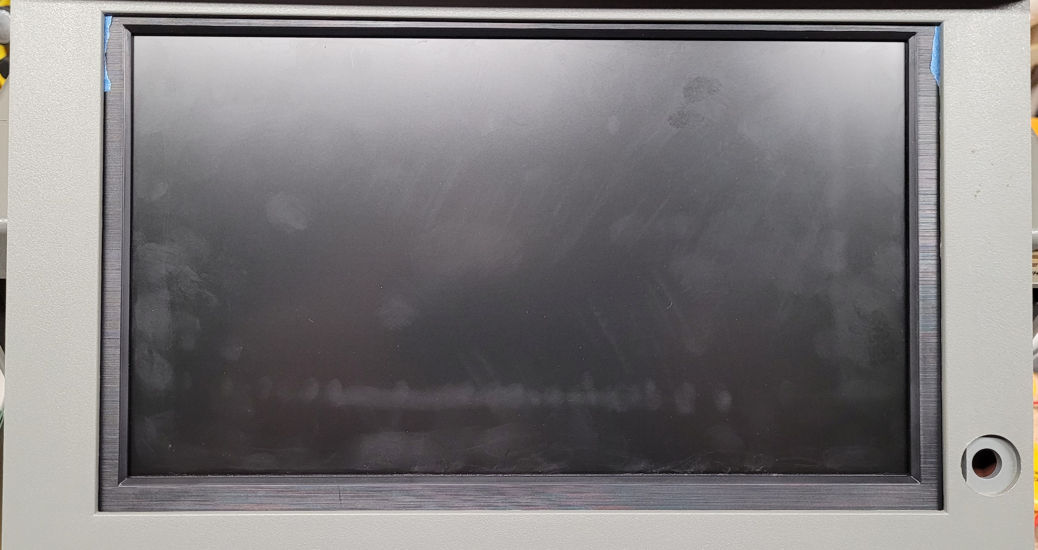
This new display is actually larger than the old one but theoretically still able to fit into the display housing - we'll find out...
Testing, Selecting and Fitting a Motherboard
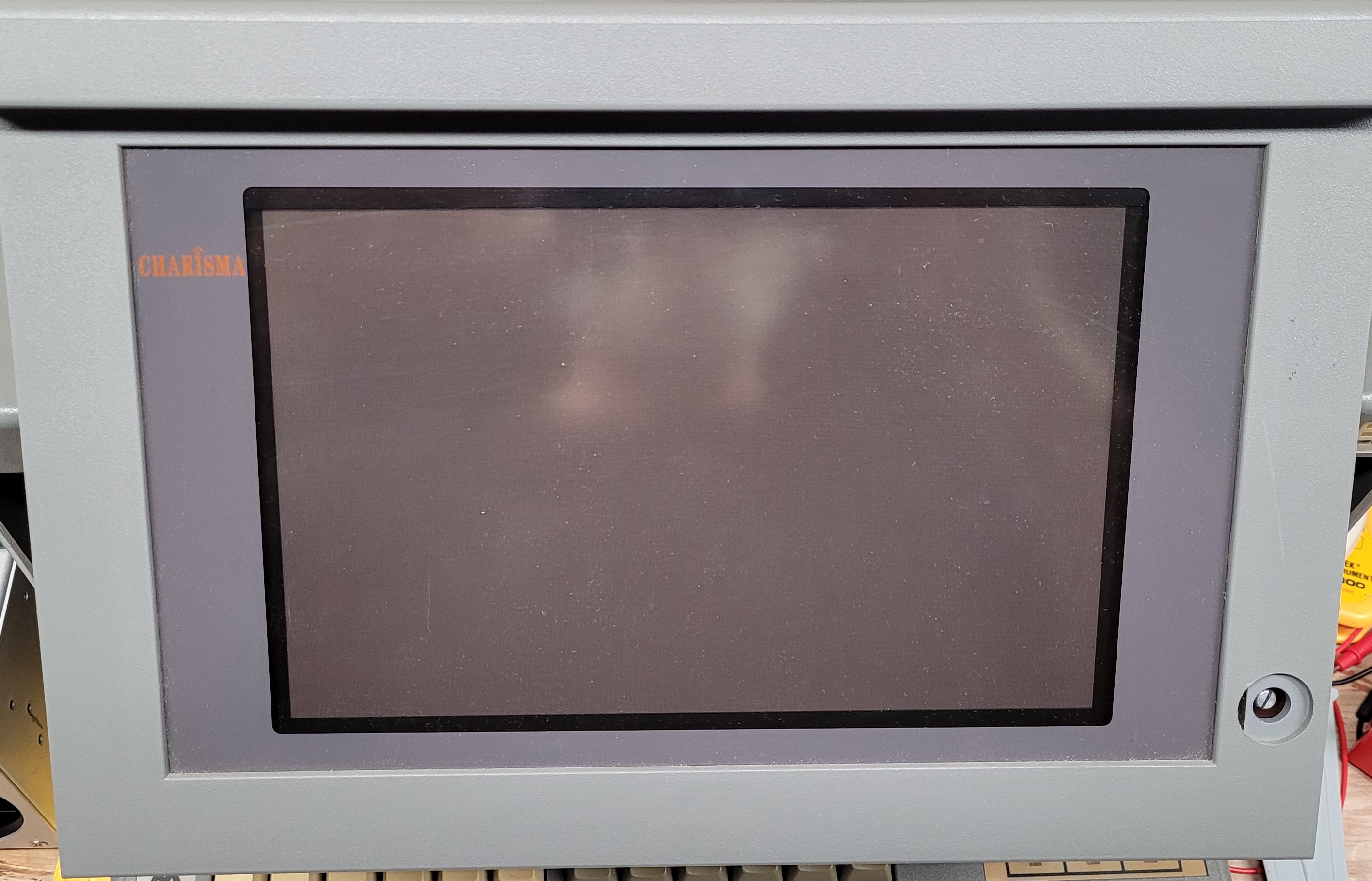
This is the plasma display with the
clear plastic screen protection in
place. You can see the darker gray
surrounding the smaller display.
Note also the screen brightness /
contrast control in the lower right
corner (knob already removed).
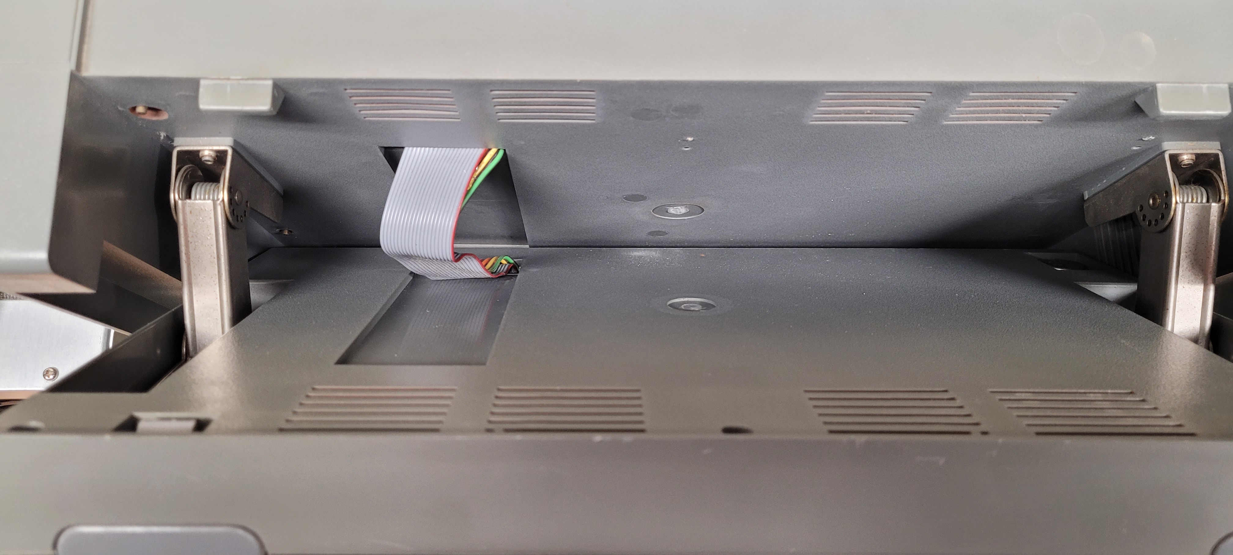
In the photo to the right you
can see the display cable path
that will be used to install the
new cabling for the VGA
display. See also the screen tilt
mechanisms on each side.
There are detents for various screen positions.
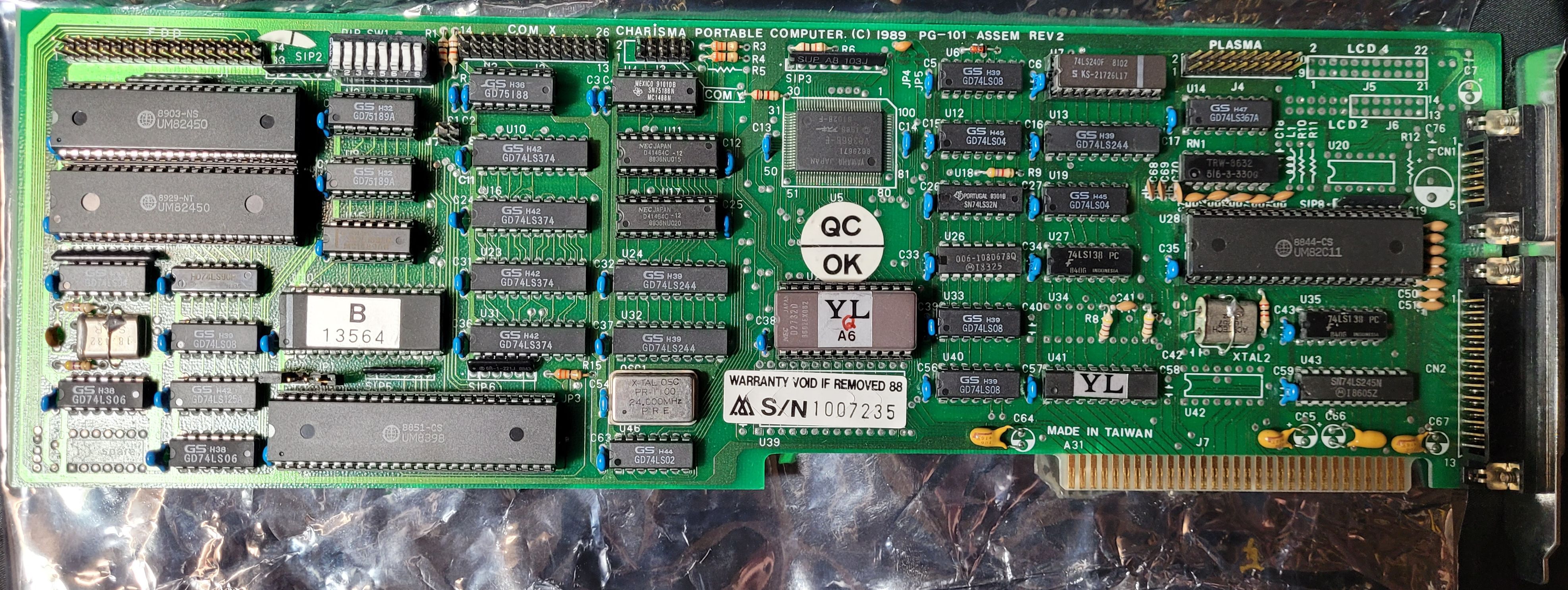
Here's the display interface board for the
plasma display. I had a dual-row header for
the old display's ribbon cable to plug into.
The plasma display's high voltage was
generated in the computer's main power
supply.
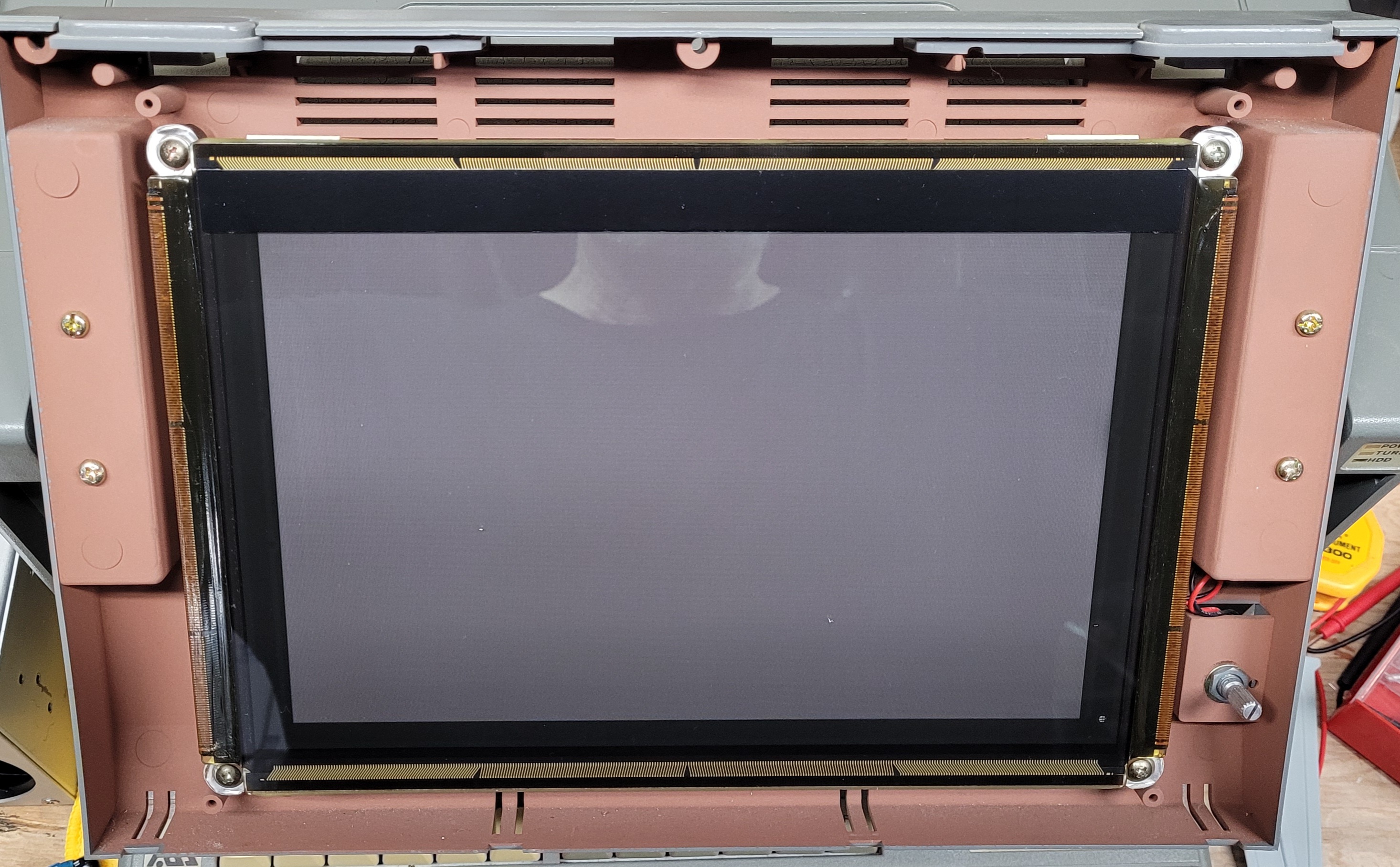
To the right is the opened up
display housing showing the
plasma display. Removing the 4
screws allowed removal of the
display, then came removal of
the brightness control to clear
the housing.
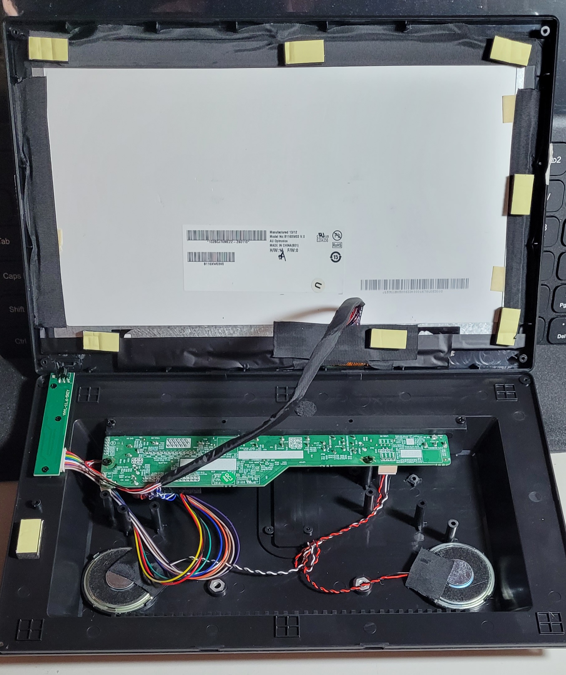
Pre-mod color display, prior to
disassembly and modification to
fit inside the lunchbox screen
housing.
Removal of four screws revealed the interior of the "HD" display (as advertised) showing
the screen back, video interface board, speakers and control board (left side). Everything
was removable with screws except the screen which was attached with double adhesive
tape.
I removed everything except the speakers (not using) and began figuring out how to fit each item into the lunchbox screen housing. The first step was to do some measurements to see how much clearance I had within the housing to determine if there was indeed enough space to fit the thickness of the screen/frame assembly in and still close the front cover flush with the screen frame. I had already abandoned the idea of adding an extra plastic protective layer... laptops don't have it so why would I need it here? So with that decided I just layed the framed screen inside the front housing cover and it fit well and looked great! I could see that some trimming would be required so then began removing the screen from the frame and did some trimming using a Dremel tool.
I removed everything except the speakers (not using) and began figuring out how to fit each item into the lunchbox screen housing. The first step was to do some measurements to see how much clearance I had within the housing to determine if there was indeed enough space to fit the thickness of the screen/frame assembly in and still close the front cover flush with the screen frame. I had already abandoned the idea of adding an extra plastic protective layer... laptops don't have it so why would I need it here? So with that decided I just layed the framed screen inside the front housing cover and it fit well and looked great! I could see that some trimming would be required so then began removing the screen from the frame and did some trimming using a Dremel tool.
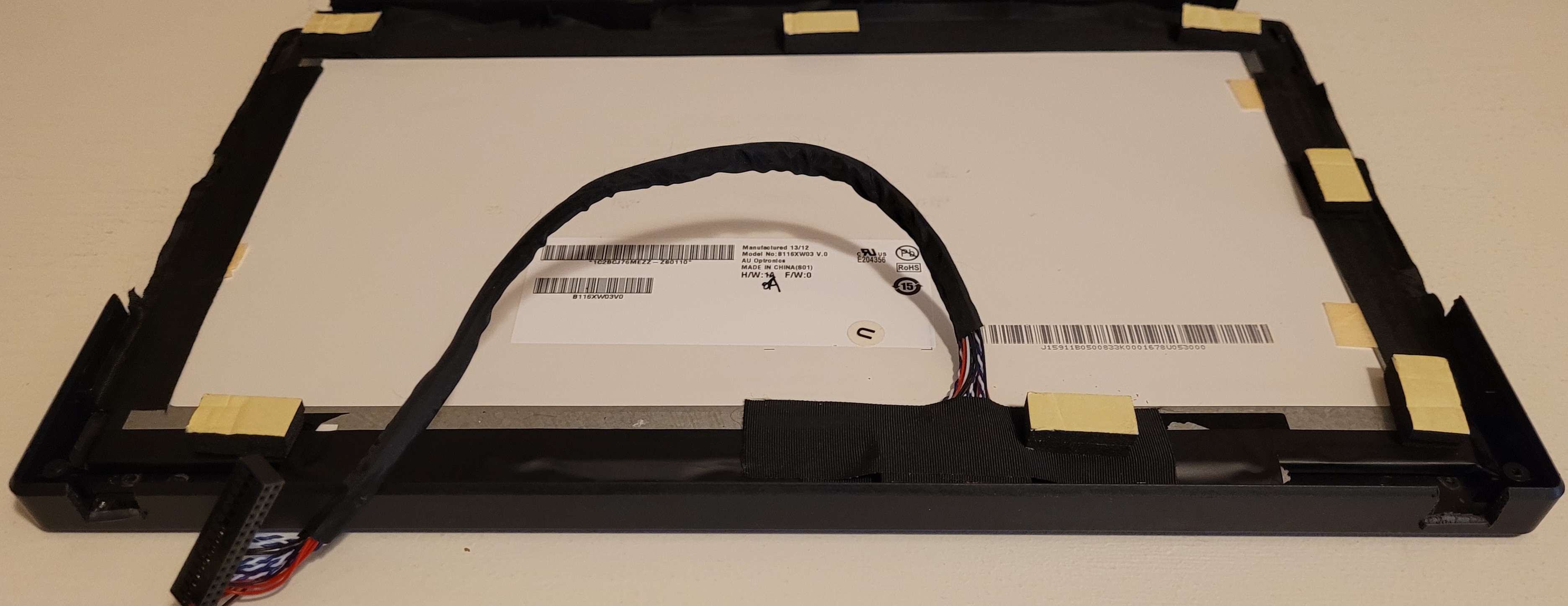
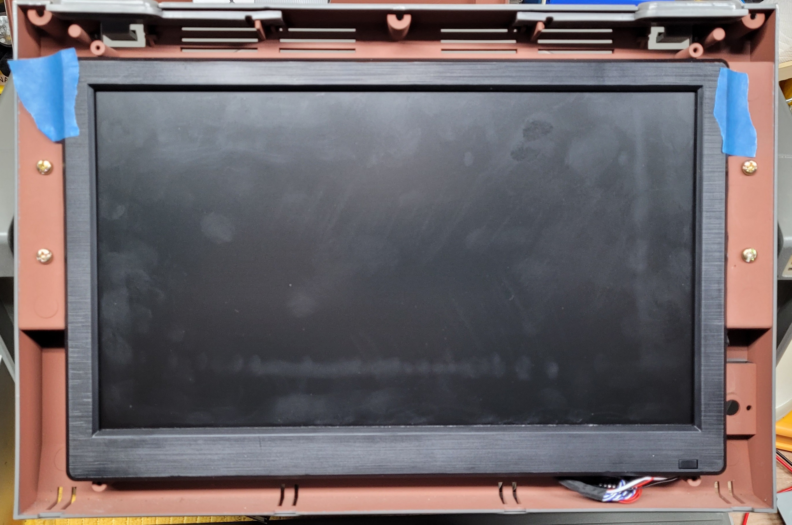
Here's the trimmed screen frame. As you can see
there was some of the side edges that needed to be
completely trimmed away so the screen assembly
could fit deep enough into the housing. This shows
the screen already re-installed but I did the trimming
with the screen out of the frame just to be safe.
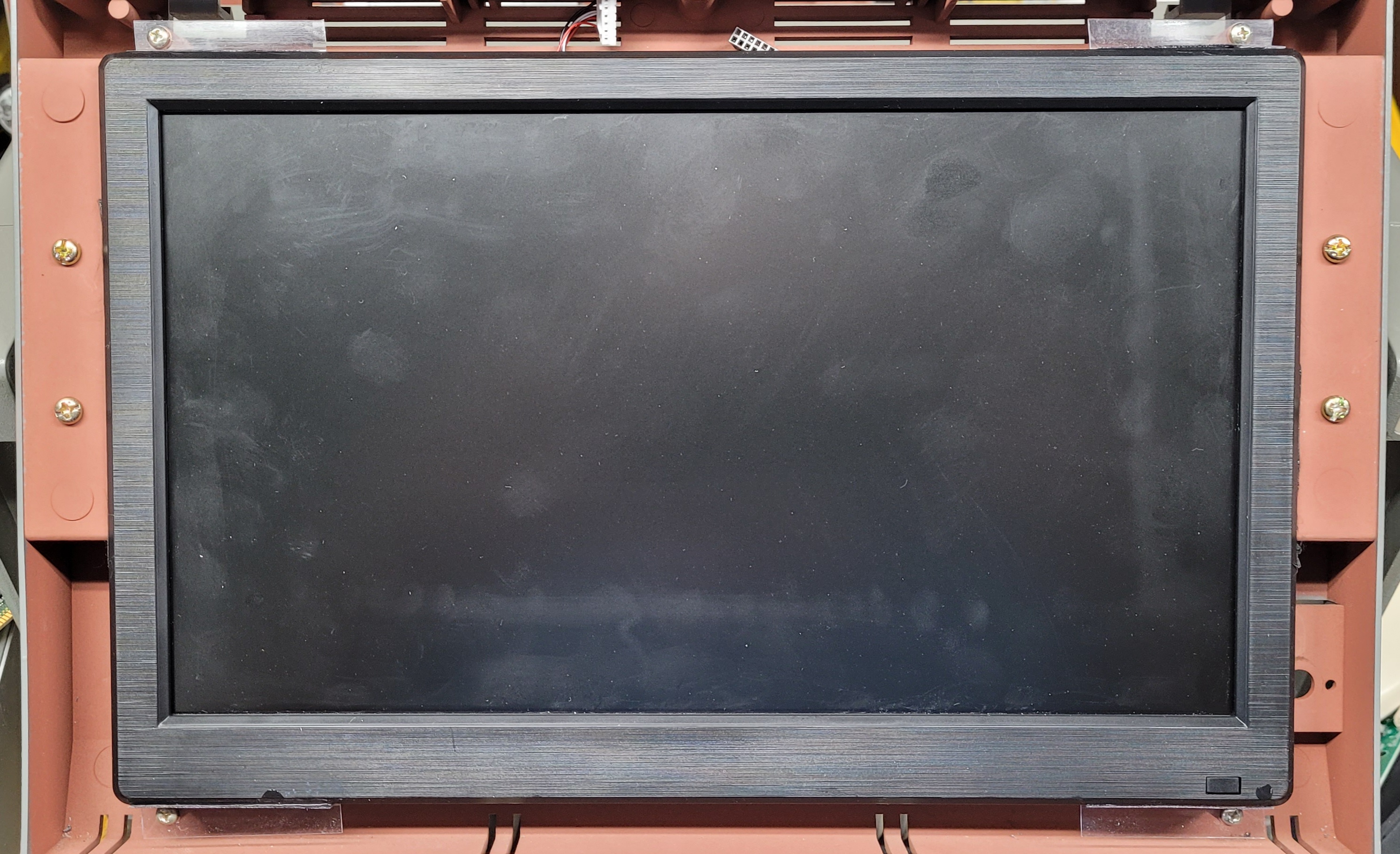
Here the housing front
cover is in place and you
can see the fit was perfect!
The screen frame face is
almost touching the cover.
Here the screen is taped
in place for a housing
fit-check... looks good so
far.
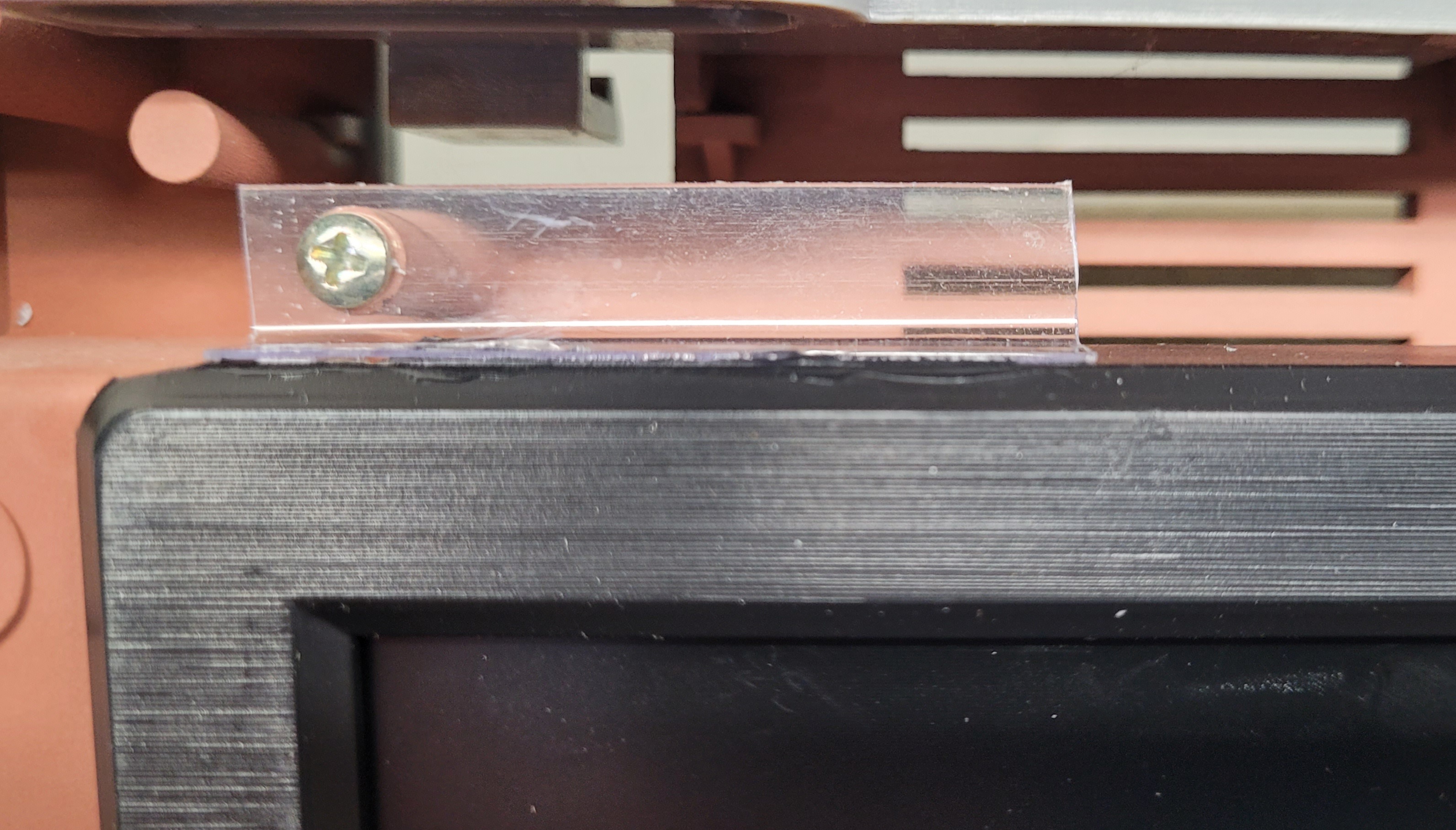
Next step was to securely mount the display into the
housing. It was challenging to find suitable brackets but I
finally settled on some right angle tabs cut from some
plastic retail blister-pack I had laying on
the garage bench. I needed it to be clear
so I could easily locate the mounting
holes. I just placed them over the posts
and marked the hole locations. Four were cut and fashioned in this way. After cutting
and drilling them, with the screen still taped in place, I attached each tab with a screw
so it touched the screen edge, then glued them in place to the screen with superglue.
I waited overnight to let the glue fully harden, then removed
the screen from the housing so I could work on mounting the
interface and control boards into the housing.
One concern was... is there enough clearance between the housing back
and the back of the mounted screen? So I got that measurement and
determined there was enough room using 1/4" standoffs to mount the
interface board. I laid the board in place and stuck a pencil through the
mounting holes to mark where to drill for the standoffs. Did the drilling and
mounted it up. Re-checked for clearance and all was good. Mounting the
control board was a little more complicated. It needed precise spacing
from the inner surface of the housing to work properly with the buttons.
Additionally, the holes for the buttons needed to be precisely
drilled and the board needed to be precisely placed above the buttons for them to be able to actuate the switches on the board. That's a lot of 'precisely's!
I decided to use the actual posts from the original monitor plastic housing since the spacing would then be 'built in'. I used my best pair of flush-cutters
and removed the mounting posts from the orignal housing and attached them to the control board using the original hardware screws. I then took some
precise measurements of the button centers and diameters and picked the appropriately sized drill bit. The hole centers were painstakingly marked and
center-punched on the side of the display housing, drilled, and fit-checked with the buttons. All good so far... I then mixed up some 5-minute epoxy and
put a glob of it on each of the three already attached posts to glue them to the display housing above the button location. I slowly adjusted the position of
the board over the buttons until I got the best 'feel' pushing each button in turn. I held the board in place with pressure, still checking to be sure the end
buttons worked correctly, until the epoxy had set up stiff enough to let go after which I just left it alone overnight. A check the next morning verified all was
still well. The setup selections stay in the interface board memory so the buttons may never even need to be used, but they are there just in case.
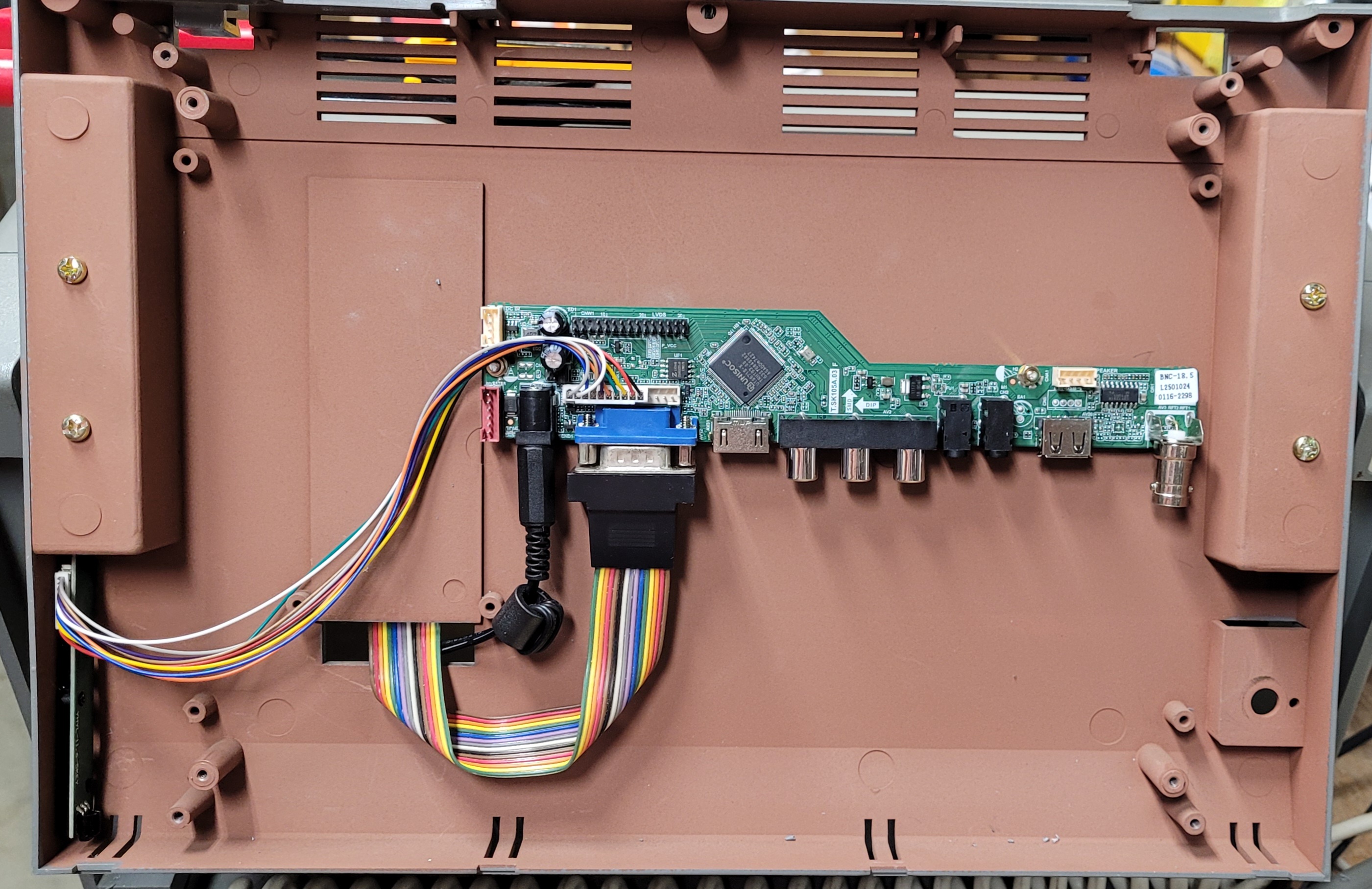
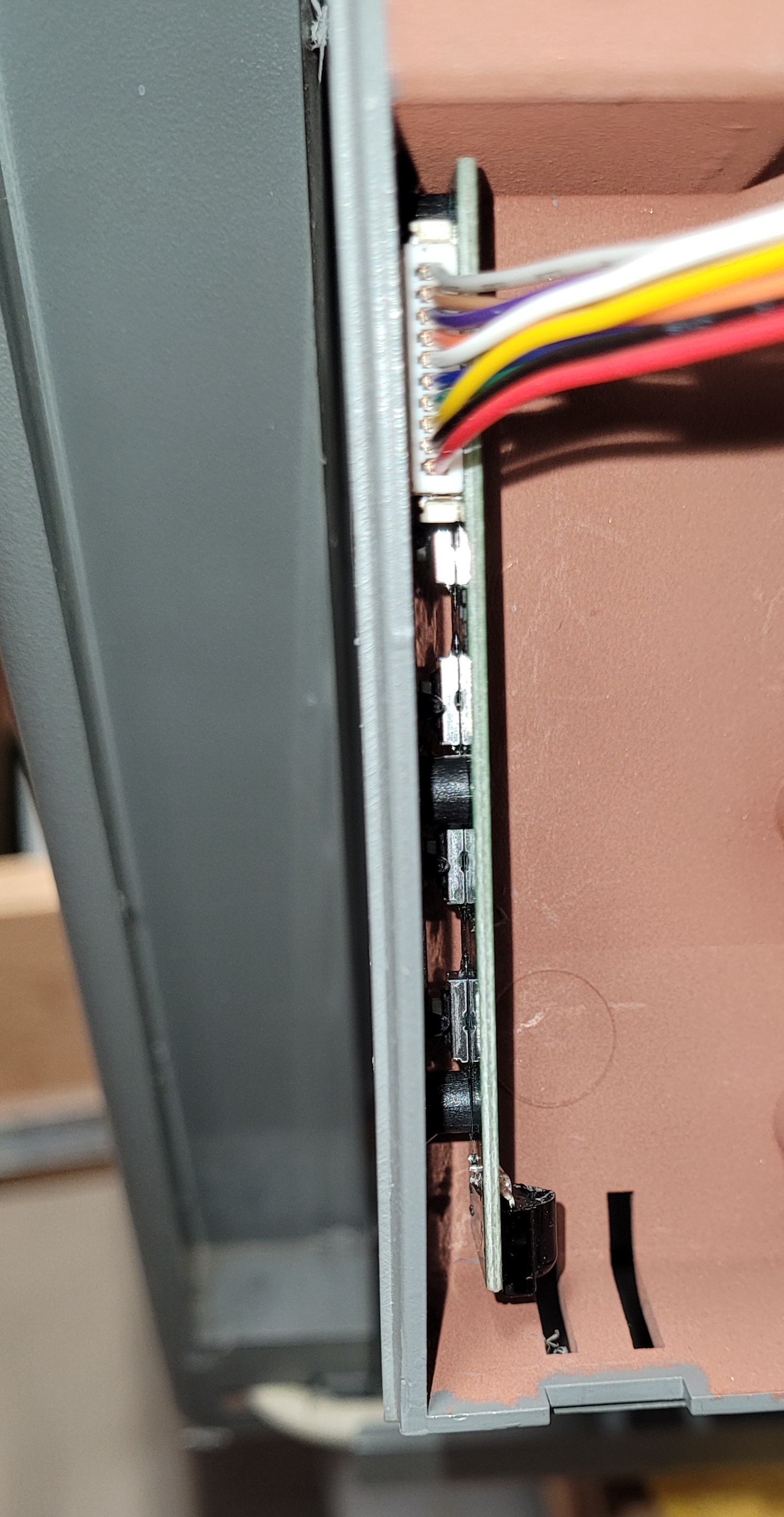
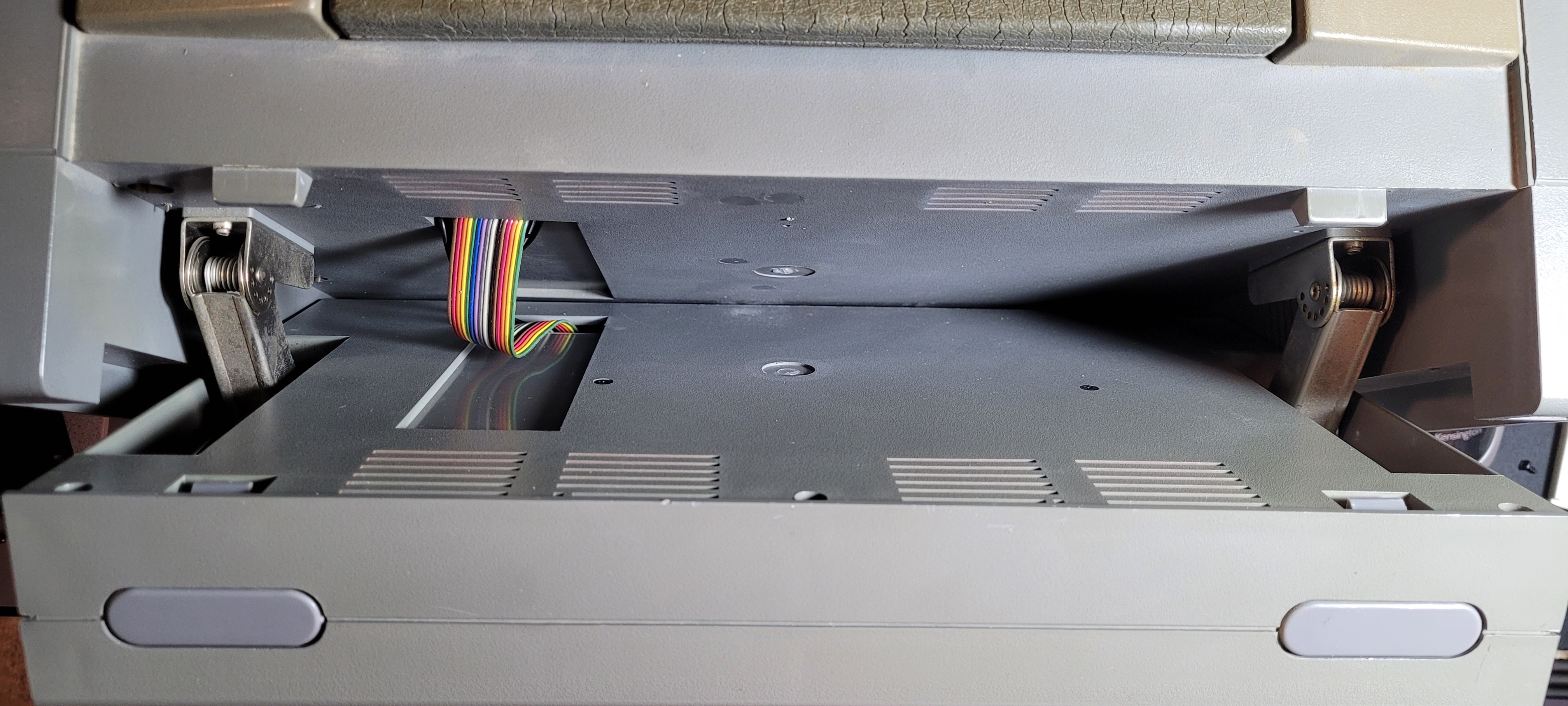
Here are some views of the routed VGA
(rainbow cable), display power, and ATX
power button cables. To the left are the
3 cables going from the display housing
to the main cabinet via 2 slots, one in
the back of the display housing and the
other in the front of the main housing.
The cables then route under the
motherboard to their destination points
as shown to the right.
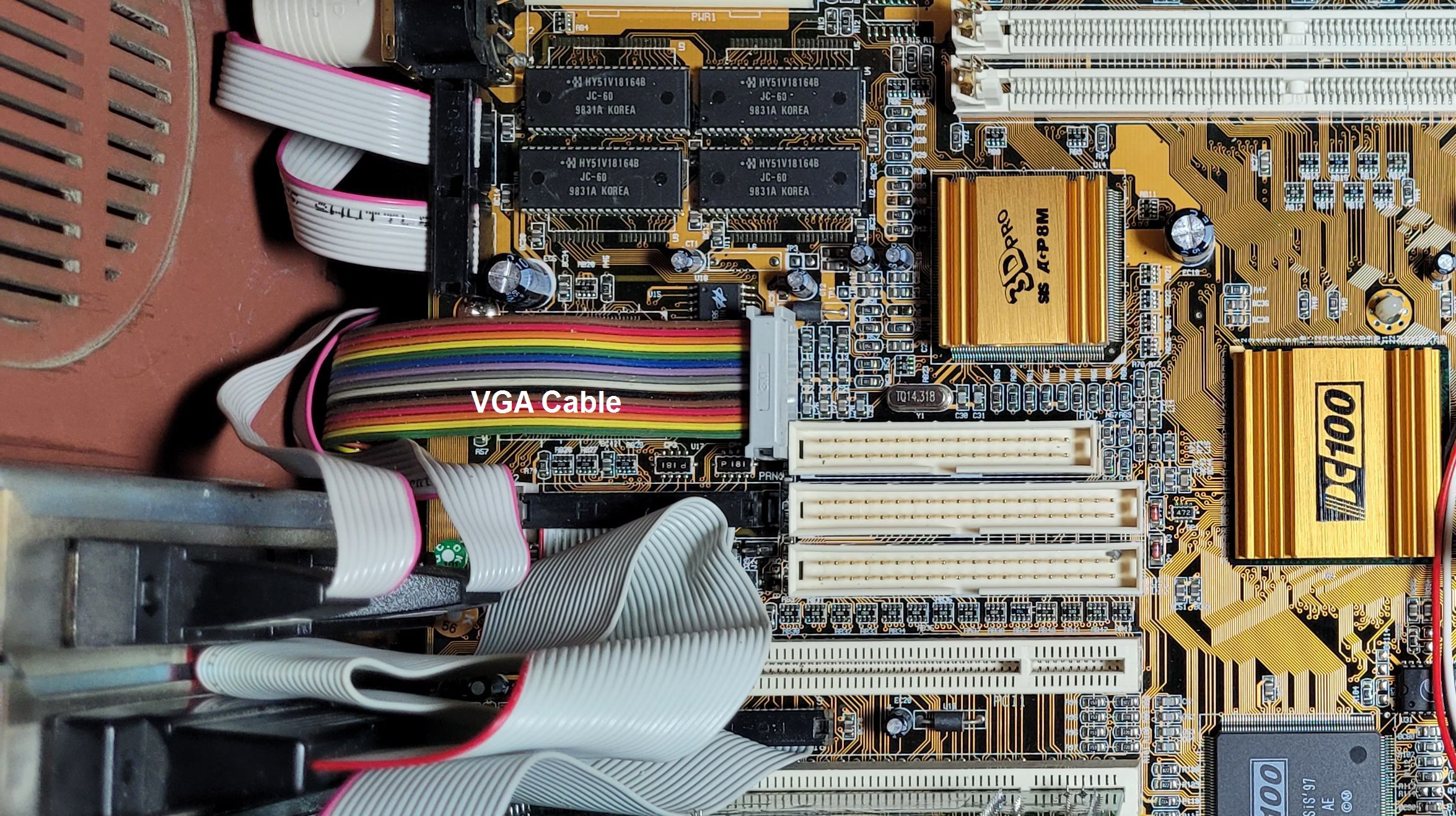
VGA cable is the rainbow ribbon cable. Look at the larger pic to see
the ATX power and screen power cables. The ATX power button was an
add-in, installed in place of the old plasma screen brightness control.
FINAL ASSEMBLY AND TEST
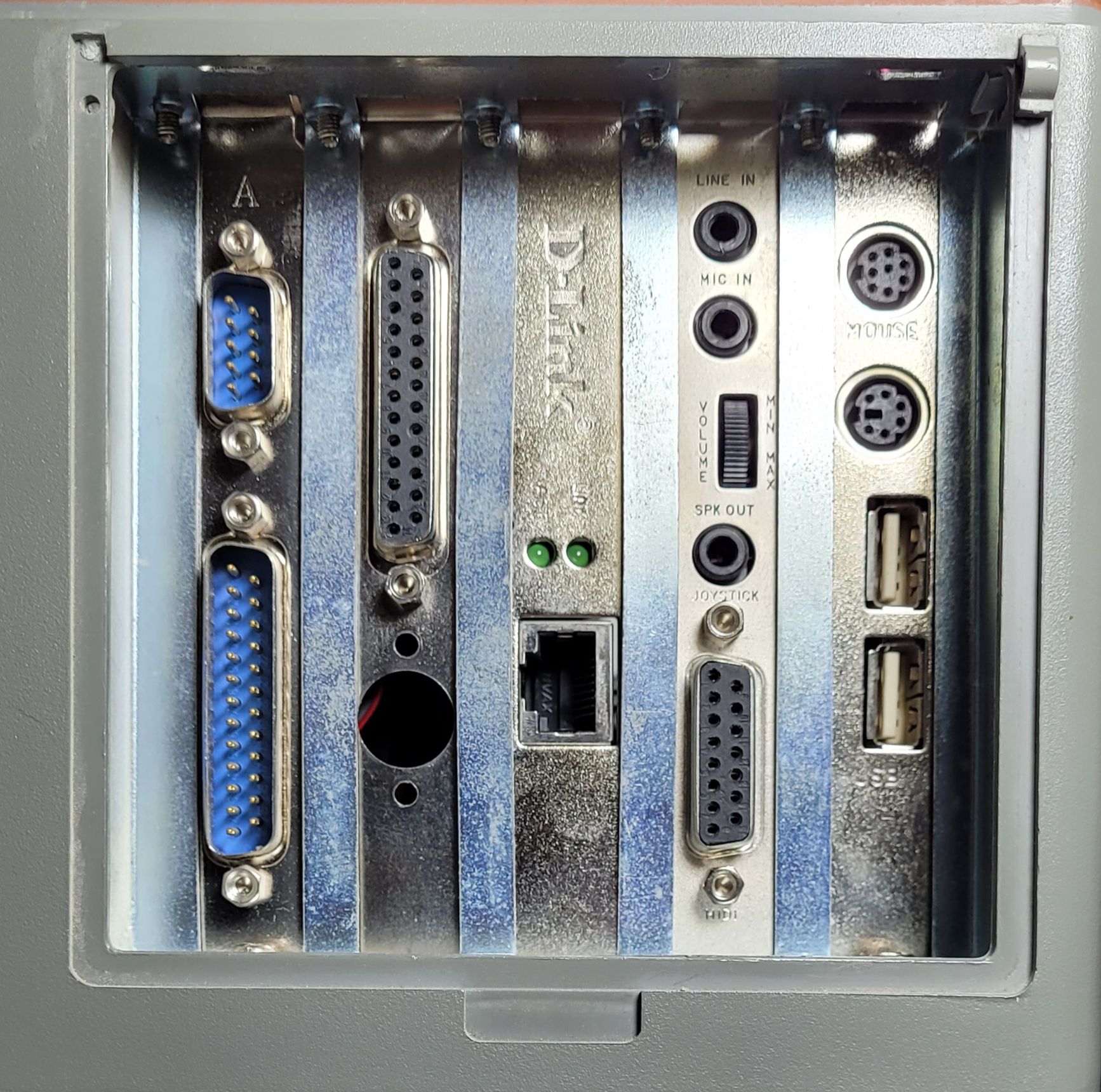
With the display now installed into the display housing and connected to the mother board it's time to plug in the few cards I have
room for. Since the serial, parallel and USB ports (all direct connected to the motherboard) are taking up 3 of the 5 available edge
slots I have room left for two cards. I use one for an ethernet card (plugged into a PCI slot) and an old Sound Blaster Pro card I
have (16 bit) plugged into an ISA slot.
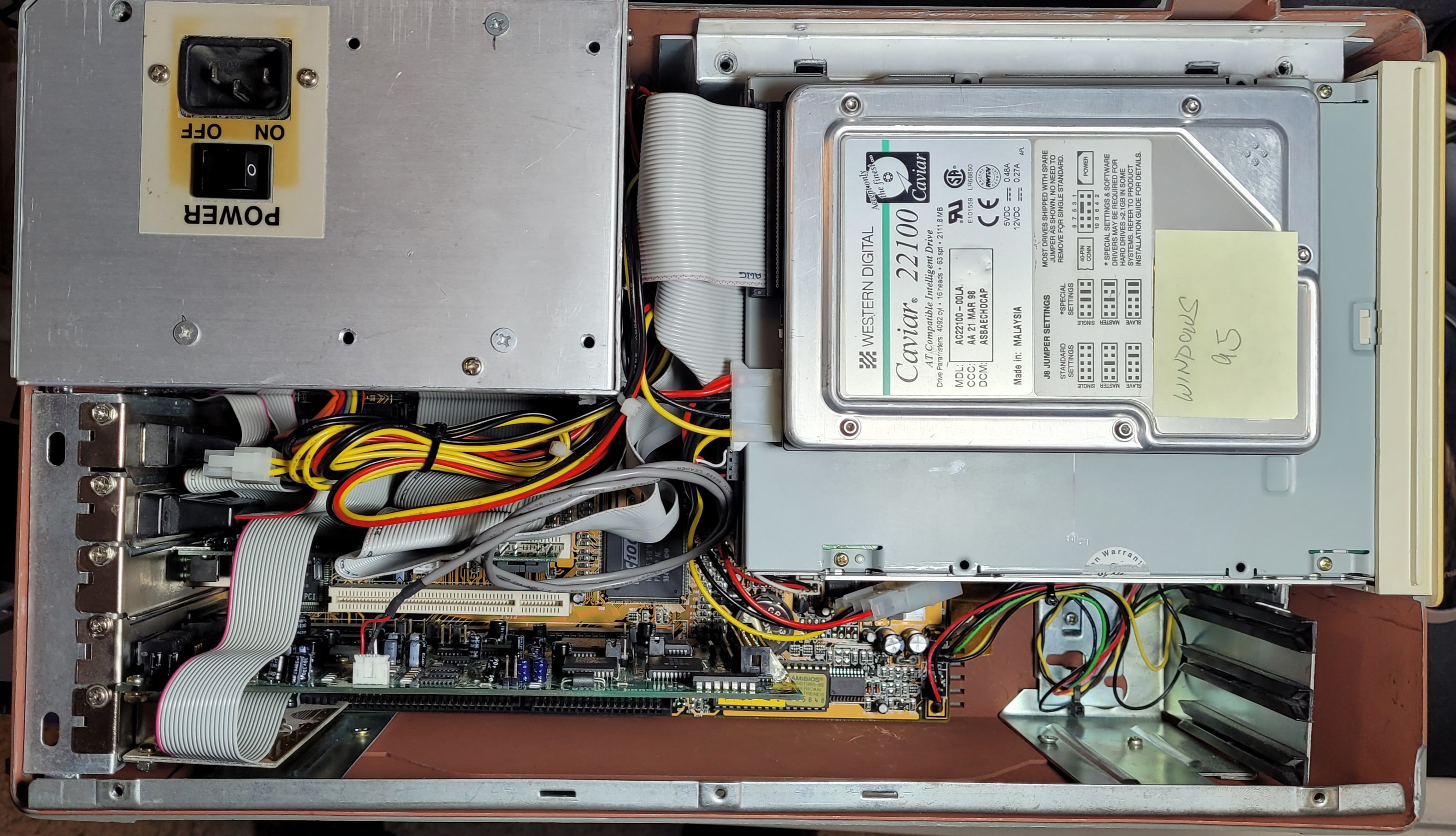
It's a little hard to see the details in such a packed space, but everything's in there including an HDD which I
hard mounted directly to the top of the CDR drive. That worked out well as there was enough clearance beteen
the top of the CDR drive and the inside of the back cover. All that's left to do here is mount the back cover.
Here's a view of the 5 slots
on the left side of the unit.
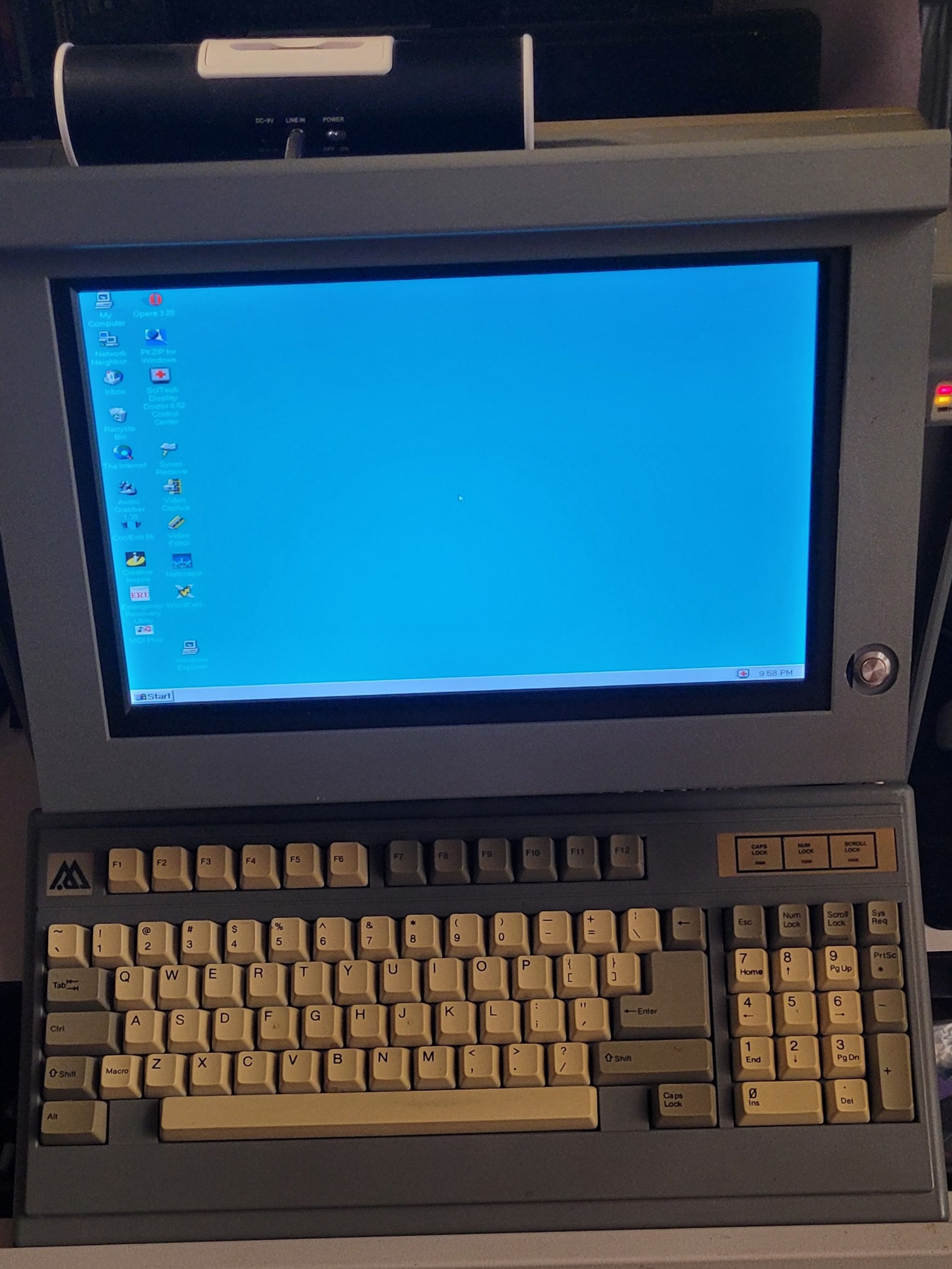
And, finally, the operational upgraded
Charisma lunchbox computer sporting a
Windows 95 operating system (that's what
was already on the HDD). The little tube
speaker on the top is connected to the
Sound Blaster's audio out port. I'm not
much of a gamer but I did load up Doom for
nostalgia's sake and the video and sound
were just as I remember them from years
ago when the game first came out :)
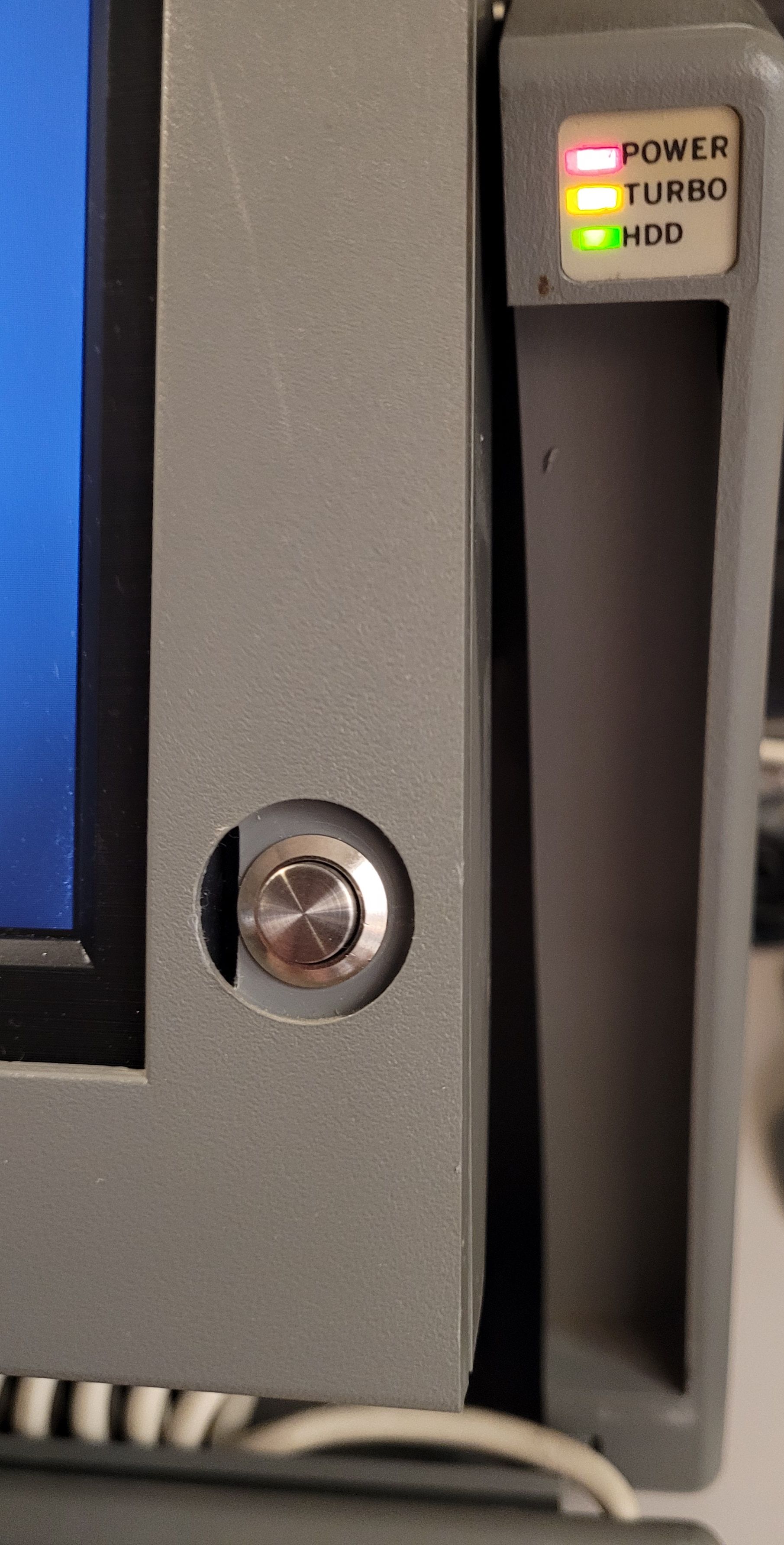
The power button works as expected, so the power switch is left on in the back and the computer can be powered up with the button.
The power button works as expected, so the power switch is left on in the back and the computer can be powered up with the button.
FINAL THOUGHTS
This has been a fun project, FINALLY getting this old relic fully operational and even usable to some degree after so many years of
having it in storage. I would like to find some version of Linux that will run on such a limited machine and will load up a hard drive (or
SSD) if/when I find it. In the mean time I might try loading up a drive with XP and putting it in there. I have quite a few older computers
with XP and am pretty attached to it as an operating system. Of course you need to be careful using it online.
The keyboard leaves a bit to be desired... I didn't realize it at first but there is no 'Delete' key (no, the backspace doesn't work as a delete key - I tried) which I need to get into bios setup. So when I need to do that I have to connect a USB keyboard that has DEL and then I can get into bios setup. I'm toying with the idea of hacking up the keyboard to place an appropriately sized 'normal' keyboard in there, but maybe I'll just do a 3D print instead of hacking up the actual keyboard top. I have a good bit to learn about 3D printing before I can do that though so won't be jumping in that direction for a while, if I ever do.
I really enjoy finally having a nice quality color display in this thing and am pretty pleased how well the screen retro-fit worked out. I really didn't think it would be that easy but as it turned out, it wasn't bad at all. The surprise of finding that I had a motherboard with and on-board VGA port that could be wedged into this case was most satisfying and really made my intended (less kludgy) implementation possible. How often does something like that happen? :)
It was a bit of a challenge finding all of
the driver / software disks for the
installed boards and the motherboard,
but I keep stuff like that and it was just
a matter of hunting until I found them,
and then doing the installation and
testing afterward.