|
|




Korg Monotron Modification Project
After reading more about the Monotrons I had purchased at the time I discovered that they were very modifyable due to the
engineers that designed them putting pads with clear labels of the locations of the synth's functions on the PC boards, and not only
that, Korg decided to make the schematics avaialble to the public. Well, let the modding begin! There are mods of these things all
over the internet so you don't have to look far to find one to your liking, or just get the schematic and implement your own ideas. I
have all three monotrons but have only modded the original monotron so far. Following are photos of what I did along with some
descriptive text.
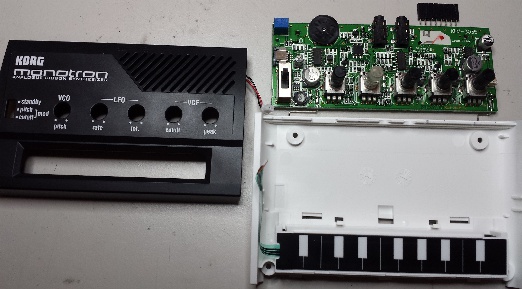
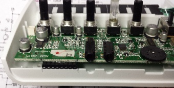
Assuming you have a monotron in hand, the first thing to
do is remove the screws and open it up. Be careful with
the ribbon cable - carefully pull it out of the connector on
the PCB. The speaker connector must also be
unplugged. This frees up the PCB for the mods. You can
see the 8-pin receptacle header sitting just above the
location where it will be glued to the bottom of the PCB.
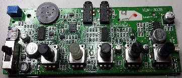
Below is a PCB closeup.
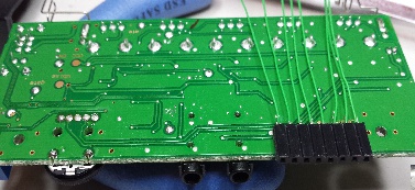
Here is the underside of the PCB showing exact header positioning. Note that the
wires are already soldered to the header before it is attached to the PCB (see below). I
used 30AWG wire-wrap wire for the connections. Also note the slight overhang of the
header off the edge of the board. This is to extend the header through the back of the
case.
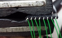
For attachment I used 5-minute epoxy, the standard stuff you can get at any hardware store. You usually mix it 50/50 and I've found it best to use a post-it note sheet (holds it still) and squeeze out small equal amounts of each part and stir / fold them together using a toothpic. Once it's mixed completely (takes less than a minute) just add some
For attachment I used 5-minute epoxy, the standard stuff you can get at any hardware store. You usually mix it 50/50 and I've found it best to use a post-it note sheet (holds it still) and squeeze out small equal amounts of each part and stir / fold them together using a toothpic. Once it's mixed completely (takes less than a minute) just add some
to the side of the header that will be against the board
and carefully position it while squeezing it against the
board. Tape can be used to hold it in place for the few
minutes it takes for the epoxy to begin hardening.
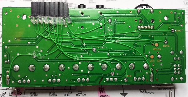
Here's my fully modified board. I used hot-melt
glue to tack down all of the leads to the board
surface and around all the header connections
to give the wires some strain relief while moving
them around, cutting them and soldering down
to the pads. The header offset (off the edge of
the board) is a bit easier to see in this photo.
The header connections to each of the TP points on the board is shown below the board photo.
Pin 1 of the header is closest to the left side of the photo. This would be the right side of the assembled monotron as viewed when looking at it from the normal operating position.
The header connections to each of the TP points on the board is shown below the board photo.
Pin 1 of the header is closest to the left side of the photo. This would be the right side of the assembled monotron as viewed when looking at it from the normal operating position.
Now it's time to complete the project -
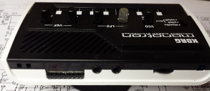
The photo to the left shows how to mark the case bottom for the header slot. Just lay the board in place where it will be and mark at each side of the connector adding a little extra for good measure. Then use an exacto blade to cut the back down to the base and break that piece off using pliers. Trim smooth with the blade then set the board in place making sure the header fits all the way down and the board is flat against the mounting points. Then install the top and then the 4 screws... you're done! All that's left to do now is to try it out! Note that battery power is available at pins 7 & 8 if you want to use that on a protoboard to power whatever circuit you might choose to build.
The photo to the left shows how to mark the case bottom for the header slot. Just lay the board in place where it will be and mark at each side of the connector adding a little extra for good measure. Then use an exacto blade to cut the back down to the base and break that piece off using pliers. Trim smooth with the blade then set the board in place making sure the header fits all the way down and the board is flat against the mounting points. Then install the top and then the 4 screws... you're done! All that's left to do now is to try it out! Note that battery power is available at pins 7 & 8 if you want to use that on a protoboard to power whatever circuit you might choose to build.


