|
|


RB5X Manual Drive Controller
This page details a quick project my grandson Logan and I worked on together for his high school engineering class. RB5X is very
old and hadn't actually moved around for at least 10 years, so we decided to do a quick and dirty project to manually get it moving.
Normally it would move around under program control but this method has proved almost fruitless as it's difficult to communicate
with the robot using the old existing software methods. Plus we needed something fairly quick for a project so coming up with a
more straightforward method of motion control was in order. Below are some details on how it was accomplished, after which we
recorded a final video as proof for the teacher of his work. Click on each photo to see an enlaged version.
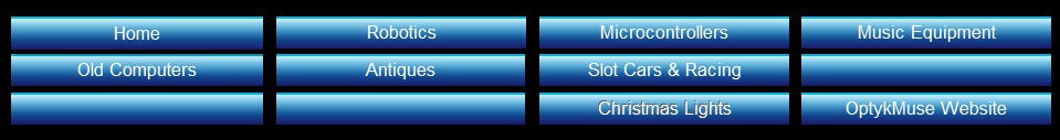
Here's RB5X just sitting, wanting to be able to move around like other robots do... try as he might, nothing happens. He either
needs some software to tell him how to move or, in this case, we will provide him with an easy way to move as along as his human
overlord is present to push the control buttons in the correct manner. We could carry him around but what fun would that be?
Let's get busy building a control box that will connect to his motor control board and enable RB5X to move forward, backward, in an arc, spin in place, or any combination of the above, all under human control of course.
Let's get busy building a control box that will connect to his motor control board and enable RB5X to move forward, backward, in an arc, spin in place, or any combination of the above, all under human control of course.
This was a fun project, especially working with my grandson on it. I think this addition to RB5X will be useful, and even more so if
we add a connector to the control panel on the robot so the control box can be plugged in only when it's needed to move the little
'bot manually. This will require a little thought and some looking at the schematics and a datasheet or two to be sure we can
make connections in parallel with the existing drive connection without damaging the driver chip or whatever is driving the driver
chip (from the microprocessor board). Implementing this should make a great one day project in the near future.
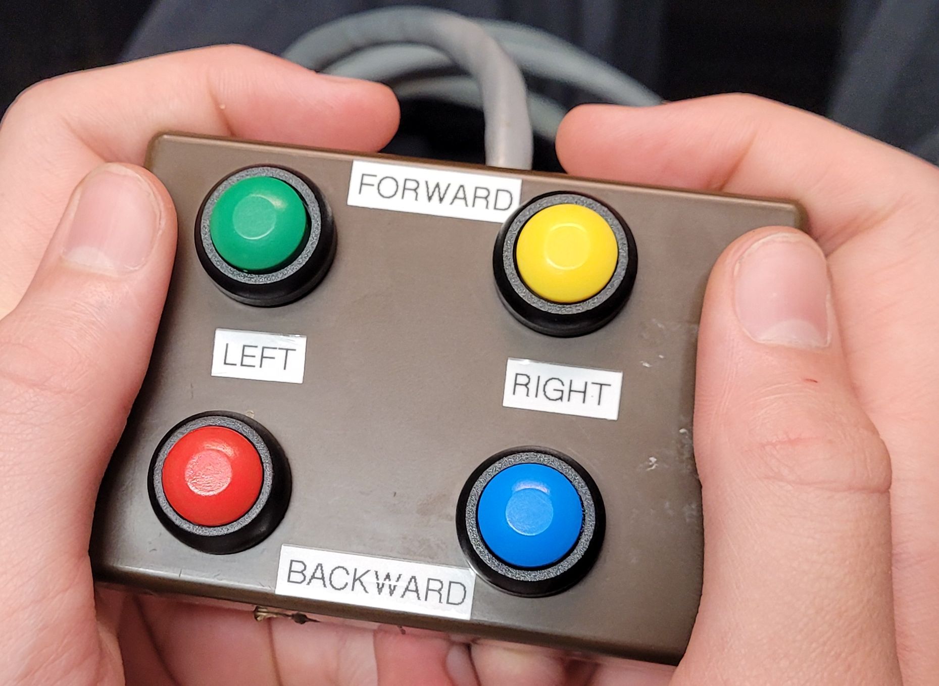
The drive components are on the floor so let's flip RB5X over and
take a look at the drive board to see if there might be a convenient
way to gain control. If you look to the right of the IC there is a
ribbon cable plugged into the board, and there are a few other plug
connections along the lower side also. These lower ones look like
power connections so it appears that the ribbon cable should be
the control inputs to the board. A look at the schematics confirms
this. So here is our way to gain control of the motors... we just
need to figure out which pin is which on the connector.
Schematics are like gold to anyone trying to analyze how something works or to troubleshoot a problem with some device. This
schematic was from the RB5X manual which, in addition to providing detailed explanations of how everything works in the robot,
also contains complete programming instructions and schematics and interconnections for everything inside the case, as well
as the charger. This was enough information (along with a datasheet for the ULN2003A driver chip) for us to determine how to
build the manual controller we will use to move RB5X around.
We used this info to determine that positive logic signals were needed to switch each driver chip output to ground to actuate relays K0 thru K3, which in turn provide power to the motors to drive them in one direction or the other.
We used this info to determine that positive logic signals were needed to switch each driver chip output to ground to actuate relays K0 thru K3, which in turn provide power to the motors to drive them in one direction or the other.
We went through the bench supply and the bins and
boxes of surplus stuff in the garage looking for an
appripriate sized enclosure, some multi-conductor cable,
four momentary pushbutton switches and an in-line
female connector to mate with the motor control board
connector pins. we drilled out the box with holes for the
switches and one for the cable to enter. After Logan
mounted the switches he got busy soldering some wire
to connect the cable to the switches. The other side of
each switch was connected together and to a single wire
(the switch common) which will be battery positive.
We used an external battery plugged into the drive board and a
probe connected to battery plus to test each input and see which
direction it caused each motor (and wheel) to run. With this we
were able to determine which pins would provide forward direction
and reverse direction for each wheel. We now have enough
information to construct a switching arrangement to simulate the
control signals that would normally be coming from the
microprocessor board. Let the construction begin......
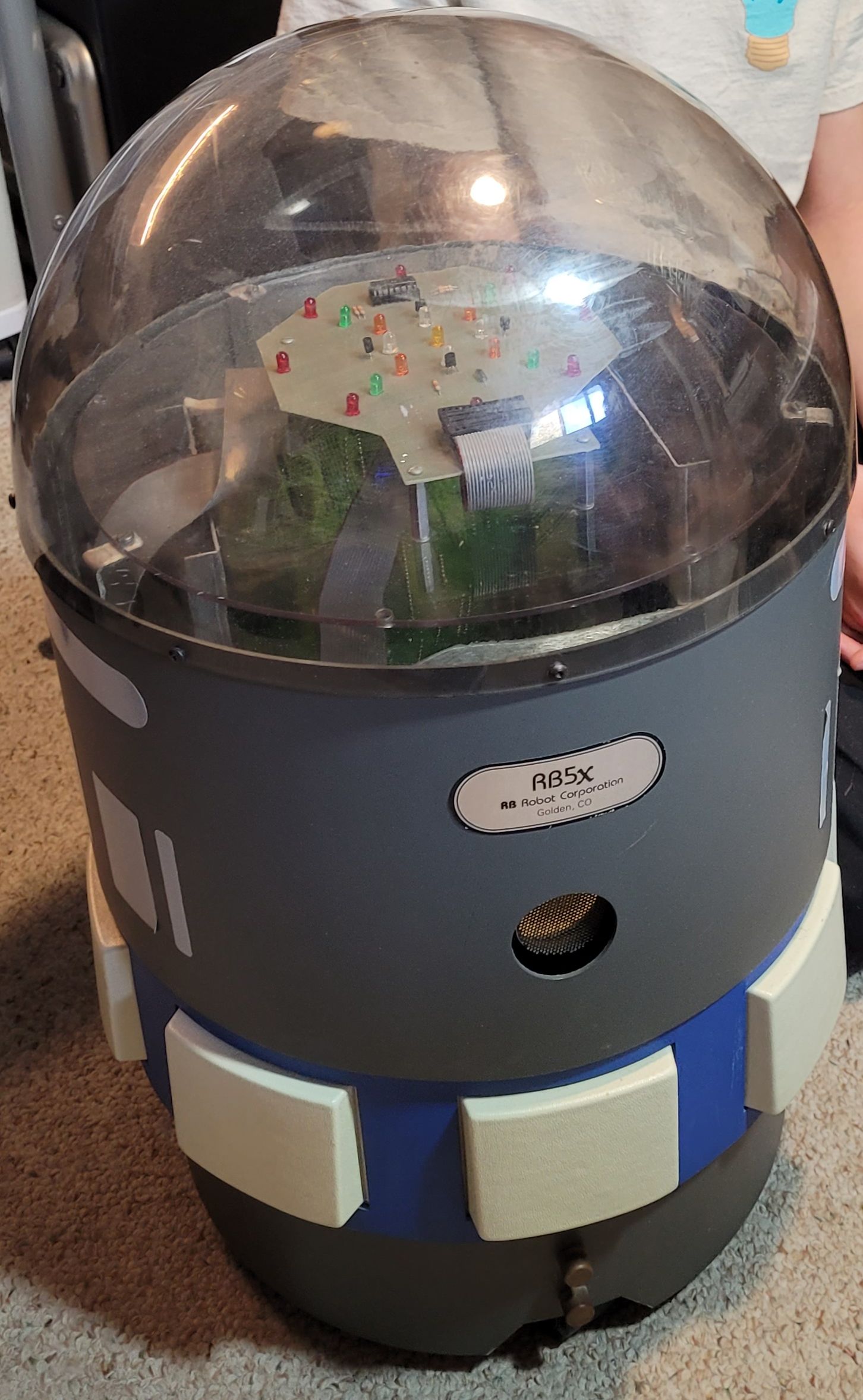
The button functions were assigned logically and labels attached to the box to make it
easy to see which ones to push to perform the various motions we needed.
The other end of the cable needs to plug into the motor control board so the buttons can actually control the motors and make the robot move.
Paying close attention to which color wire was connected to which switch, the wires were soldered to the appropriate pins of the inline connector and heat-shrink tubing was used to ensure electrical separation and to provide strain relief for the connections. After double checking all of the connections the time had come to do the "acid test"... plug the controller into the motor control board and test.
We decided, for the testing, that we would
route the cable inside the robot via the
ultrasonic sensor hole since there was just
enough room for the cable to pass through,
then routed it down through a cable port in the
bottom chassis plate to the motor control
board
There is no keying for the connector so care was taken to be sure it was plugged in with the correct orientation.
There is no keying for the connector so care was taken to be sure it was plugged in with the correct orientation.
The last thing to do... test the new control panel! We moved
RB5X into position and Logan took the controls...pushed both
the left and right forward buttons, and........... IT WORKED!
The motors were a bit cranky and noisy since they are quite old and hadn't really been 'used' for many years, but he ran it out of the lab and down the hall, turned it around, and tried several maneuvers to test everything before we ran out of time for the day. We took lots of photos and a few videos for his engineering class teacher who was very pleased with his project.
The motors were a bit cranky and noisy since they are quite old and hadn't really been 'used' for many years, but he ran it out of the lab and down the hall, turned it around, and tried several maneuvers to test everything before we ran out of time for the day. We took lots of photos and a few videos for his engineering class teacher who was very pleased with his project.