|
|


Slot Car Camera Project
I was racing one evening and the thought occurred to me that it would be great fun to be able to see what the racing would look like
if I were actually a tiny driver inside the car as it was quickly darting around the track, and what it might look like when a crash
happens. This was the start of a fun little project. I had seen very small wireless RF cameras and thought I could install one of these
on one of the slot car chassis I had in my box. This page details the thought process and steps I went through while constructing my
camera car. Most of the photos will have a larger photo to see if you click on the ones below.
There were several things I needed or wanted to consider prior to starting the build.
* Try to keep the center of gravity as low as possible to preserve the handling of the car as much as possible.
* Provide separate power for the camera, to (hopefully) minimize the noise in the power, as opposed to using track power.
* Try to dampen RF (or is it EM?) noise caused by the sparking motor brushes and sparking guide flag brushes.
* Provide a clear forward view from where a driver position would be if there were an actual driver.
* No interferance to the mechanical movements of the chassis (which would affect handling).
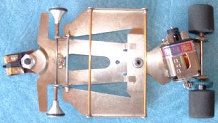
This is the chassis I chose to install the camera onto. I removed the wires that run from the flag to the motor to
get them out of the way for the build.
You can see the hole that is right in the middle of the chassis... I drilled there since that is the non-articulated part of the chassis and I wanted the body to still be able to move freely. The bottom of the hole is tapered to make the flat-head screw flush with the rest of the surface of the chassis so it will not drag on the track or track braid.
You can see the hole that is right in the middle of the chassis... I drilled there since that is the non-articulated part of the chassis and I wanted the body to still be able to move freely. The bottom of the hole is tapered to make the flat-head screw flush with the rest of the surface of the chassis so it will not drag on the track or track braid.
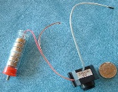
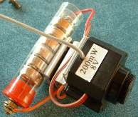
This is the tiny camera I used along with the camera power source I constructed using a small plastic capped storage
vile. I wanted very light weight batteries that would produce enough voltage to operate the camera, so settled on using
small AG13 alkaline 1.5V button cells. The total voltage with new cells is 9V which worked ok to power the camera
(even though it is labeled 8V). Click the photo to see a larger one to see the details better...
The contacts for each end were made using a flat washer and a small spring for the positive (flat) end and a #4 machine screw, two nuts and a couple of flat washers, with the screw head contacting the negative end of the battery. The positive power wire was soldered to the flat washer inside and routed through a small hole in the bottom of the plasic vial. The negative wire will come from the power switch when everthing is assembled together later. The battery lasts maybe 10 to 15 minutes before the voltage gets too low to power the camera. There are a few other battery options but I chose these because they are inexpensive and I had a lot of them.
The contacts for each end were made using a flat washer and a small spring for the positive (flat) end and a #4 machine screw, two nuts and a couple of flat washers, with the screw head contacting the negative end of the battery. The positive power wire was soldered to the flat washer inside and routed through a small hole in the bottom of the plasic vial. The negative wire will come from the power switch when everthing is assembled together later. The battery lasts maybe 10 to 15 minutes before the voltage gets too low to power the camera. There are a few other battery options but I chose these because they are inexpensive and I had a lot of them.
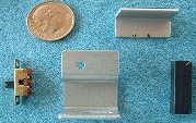
To the right are the bracket parts that would hold the battery,
power switch and camera. The larger bracket was just a random
piece that I found in my box of metal parts scavenged over the
years from various electronic equipment I've disassembled. I
didn't do any bending on it... I just needed something like it to
mount everything to the chassis. The L shaped bracket was
going to hold the battery (which I didn't have figured out yet).
The switch is to control power to the camera from the battery. I
ended up not using the black piece. The dime is just for size
reference.
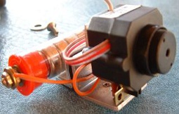
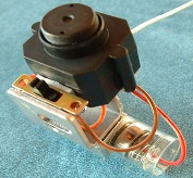
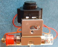
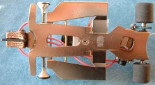
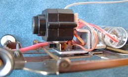
Below are several shots of the camera, battery and power switch assembled with the brackets.:
I didn't do incremental photos of this assembly but you can see from these photos, along with this description, how I put it all together.
First, note the hole in photo 2 that I drilled it to proper diameter to be tapped with 6-32 threads to accept the flat head mounting screw that will attach the assembly to the chassis you will see in one of the photos below. Ignore the oval slot - remember, these were scavenged brackets from a box of random metal brackets.
In photo 3 the switch was epoxied to the base of the bracket with generic 5-minute epoxy, being careful not to get any of the epoxy inside the switch. I chose a tiny switch I had in my surplus supply bins, but pretty much any switch you choose would be fine as long as it works with your particular design should you decide to make one of these.
Everything else was assembled using double-stick foam tape. All surfaces were first cleaned with alcohol before applying the pre-cut foam tape pieces to ensure all oils were gone and everything would stick together well. If you look carefully at the larger photos (just click each of these pics to see the larger ones) you will see the foam tape between the attached parts and brackets. This assembly worked very well and the foam thickness allowed for a little vibration during runs around the track. Nothing came apart even when the car deslotted and hit a track wall or flipped.
Note how the wires are attached to the battery terminals and how the batteries are installed inside the small plastic vial tube. The spring in the closed end keeps pressure applied so the batteries remain connected, just like in a flashlight. The red cap has enough retension friction to stay put very well even though it's just a slip-fit. The negative end (red cap) wire runs to the switch and then from the other switch terminal to the camera to control the power to it. The other end of the battery is connected directly to the camera positive lead.
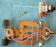
To the left is a pre-assembly photo taken just prior to attaching
the camera assembly to the chassis using the screw and
washer shown. The washer was placed between the chassis and
the camera assembly and the screw inserted from the bottom
through the washer and into the threaded hole on the camera
bracket.
The photos to the right show the attached camera bracket and how the screw hole is counter-sunk with a tapered drill bit so the screw head is flush with the bottom of the chassis.
Note also that the motor wires were installed prior to the installation of the camera assembly. Not a necessity, I just thought it would make it easier to route them without the camera in the way.
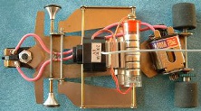
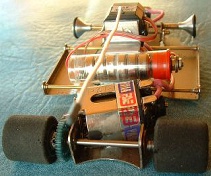
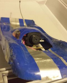
Below are several views of the assembled slot cam car as well as one with the body on it. It's just a junker body I had laying in a box and I had used it
on this chassis before, so the mounting holes were already aligned properly. Track rules where I was running it at require a body on any car on the
track and it just looks better that way anyway. The front of the body was visible in the camera view which added coolness and a more realistic view in
the video monitor I was using to see the video as I ran it around the track.
Not shown are the various filter capacitor arrangements I tried out (in vain) to eliminate the noise in the transmitted video. Still, I was able to see well enough to run the car around the track looking at the video monitor.
Not shown are the various filter capacitor arrangements I tried out (in vain) to eliminate the noise in the transmitted video. Still, I was able to see well enough to run the car around the track looking at the video monitor.
This was a pretty fun project overall, even though the video got really noisy if I really nailed it going down the straight. I just couldn't seem to
eliminate the video noise although I was able to supress it at least a little.
I have not yet been able to locate the cam car since moving to a new house a few years ago but I still have some boxes to go through and I'm sure I'll find it eventually.
I didn't have a photo of the receiver and monitor setup I used either so I should get a shot of that at some point to include here. That will give me a reason to get back over to the track and have some fun! I do have some video of the track runs (noisy as it is):
Click here to see the SlotCarCam videos
There are some updates I would like to try on this car before I take it to the track next time -
* Try a more recent camera which would probably work better
* Experiment with powering the camera via a super-capacitor charged from track power, which could keep the camera powered for a short time while out of the slot or just sitting with no power from the controller.


